So I just checked the capacitors, it raised some questions
2x2uf are suppose to be 160v but they provided 450v
2x220uf are 450v instead of 160v
2x10uf replaced by 22uf
1x47uf replaced by 82uf
Are they caps I need to get at the right value or can I go with what is provided?
Thanks
I have been out of town and didn't get back until last night so I am just getting caught up.
As was explained, you can sub higher voltage caps without much impact.
I suspect they changed the 10uF to 22uF to minimize stock.
The 10uF was part of the filter for the supply to the first gain stage. Increasing it from 10uF to 22uF improves filtering.
I think the 82uF is an error since it appears to sub for the first filter cap on the output of the rectifier tube. This cap should not be over 40uF (+/-20%) to meet the specifications of the 5U4. Modern caps are tighter tolerance so modern 47uF caps generally will fall well within the 5U4 limits. I measured two in series and got 22.5uF, indicating 45uF individually.
The 82uF could be substituted for the 47uF to the driver stage and improve filtering, but with only one that does not make sense.
When my kit arrived back in 2018 there were a bunch of parts not matching the parts list. At the time I wasn’t too sure how much deviation there could be from the schematic which was misleading in any case. Discussion with the seller was difficult due to language but stated value parts were mostly provided after a couple of emails. The few that weren’t I picked up locally.
I have been out of town and didn't get back until last night so I am just getting caught up.
As was explained, you can sub higher voltage caps without much impact.
I suspect they changed the 10uF to 22uF to minimize stock.
The 10uF was part of the filter for the supply to the first gain stage. Increasing it from 10uF to 22uF improves filtering.
I think the 82uF is an error since it appears to sub for the first filter cap on the output of the rectifier tube. This cap should not be over 40uF (+/-20%) to meet the specifications of the 5U4. Modern caps are tighter tolerance so modern 47uF caps generally will fall well within the 5U4 limits. I measured two in series and got 22.5uF, indicating 45uF individually.
The 82uF could be substituted for the 47uF to the driver stage and improve filtering, but with only one that does not make sense.
OK thanks for the explanations. I built the board with the provided parts. I was waiting for answers before powering it on.
When my kit arrived back in 2018 there were a bunch of parts not matching the parts list. At the time I wasn’t too sure how much deviation there could be from the schematic which was misleading in any case. Discussion with the seller was difficult due to language but stated value parts were mostly provided after a couple of emails. The few that weren’t I picked up locally.
Well it seems the parts they provided on my kit are for the best.
So I will go with it
Hi,
so my board is all soldered and everything connected.
There is only one thing scratching my head, it is how to connect the output transformers.
The board is labelled VCC on one PIN and a star on the other.
The star goes straight to the tube.
My output transformers have a B+ and a P wire.
Which wire should I hook to the VCC.
Thanks
VCC on the board is B+ and connects to the B+ wire of the OPT. The other "*" connection goes to the 300B plate so it goes to the "P" wire of the OPT.
VCC on the board is B+ and connects to the B+ wire of the OPT. The other "*" connection goes to the 300B plate.
Great,
Thanks, I will fire it up tomorrow. I have a relays volume control on it.
Thanks
Welle, instead of the 4x2k, I got 4x1.5k and what was suppose to happen happened, they smoked out in 2 minutes. The time check where the smoke was coming from and they melted the solder and cracked...
I also got 2x205k il place of the 2x220k.
I will change all the resistors to the right value and give it a New try.
I also got 2x205k il place of the 2x220k.
I will change all the resistors to the right value and give it a New try.
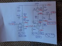
I finally got the Cascode driver built and tested for comparison to the two cascaded common cathode stages.
Cascaded Common Cathode stages:
Common Cathode dual stage was previously analyzed for un-bypassed gain (11.9) but not for Zout.
Mu = 20, Ra = 6700, Gm = 3000
Zo =(rp +[mu +1]Rk)||Ra
= (39K+[20+1]1.2K)||6700
=5292
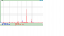
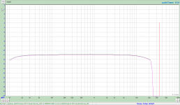
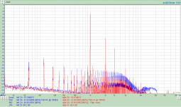
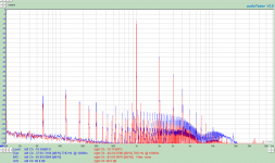
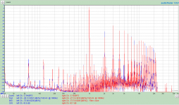
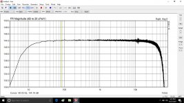
AC line voltage is adjusted to 125V for all tests.
All measurements are through a 220R/60R divider to prevent overloading the input of the sound card.
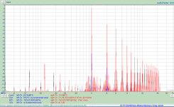
The first attachment is THD at 0.25W
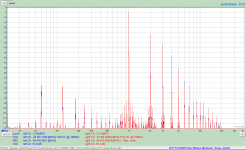
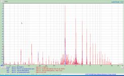
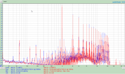
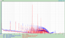
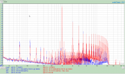
The second attachment is THD at 5.5W where it approaches 8%, but remains mainly monotonic in nature.
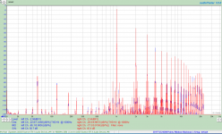
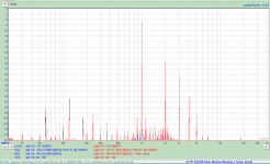
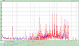
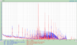
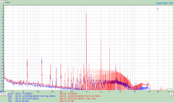
The third attachment is THD at 6.5W where it is roughly 10% and is no longer monotonic in nature.
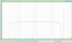
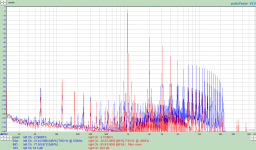
The fourth attachment is frequency response at 1W. There are two plots in the graphs, one with the coupling cap at 0.022uF, and one with an additional 0.15uF cap in parallel demonstrating that the LF response is determined by the inter-stage coupling cap and next stage grid resistor.
I prefer the sharper roll off since I have a Reel to Reel tape deck, a cassette tape deck and turntable. These can produce objectionable LF energy below 20Hz which I prefer to filtered out. If you have ever seen a bass speaker servo in and out due to record edge warp (1.8Hz) you will understand.
If all of your sources are digital, you will most likely never see such adverse effects from LF.
Cascaded Common Cathode stages:
Common Cathode dual stage was previously analyzed for un-bypassed gain (11.9) but not for Zout.
Mu = 20, Ra = 6700, Gm = 3000
Zo =(rp +[mu +1]Rk)||Ra
= (39K+[20+1]1.2K)||6700
=5292
AC line voltage is adjusted to 125V for all tests.
All measurements are through a 220R/60R divider to prevent overloading the input of the sound card.
The first attachment is THD at 0.25W
The second attachment is THD at 5.5W where it approaches 8%, but remains mainly monotonic in nature.
The third attachment is THD at 6.5W where it is roughly 10% and is no longer monotonic in nature.
The fourth attachment is frequency response at 1W. There are two plots in the graphs, one with the coupling cap at 0.022uF, and one with an additional 0.15uF cap in parallel demonstrating that the LF response is determined by the inter-stage coupling cap and next stage grid resistor.
I prefer the sharper roll off since I have a Reel to Reel tape deck, a cassette tape deck and turntable. These can produce objectionable LF energy below 20Hz which I prefer to filtered out. If you have ever seen a bass speaker servo in and out due to record edge warp (1.8Hz) you will understand.
If all of your sources are digital, you will most likely never see such adverse effects from LF.
Attachments
Cascode Driver Stage:
Cascode gain:
A = gm1 * Ra2
For a 47K Ra2 and 6SN7 this becomes:
A=3000mA/V*47000
A= 0.003*4700
A=14.1
This is considerably less than two cascaded stages with 11.9 gain each (141.61).
This will make a big difference in sensitivity. I had to turn the Cascode input pot up to 90% to achieve the listening level the cascaded CC stages achieved at 40% of the log pot position.
Rout = ra = 47K per : The Valve Wizard
This is considerably higher than the common cathode output impedance of 5292, however it makes little difference as seen on the FR plots with the roll off at 20KHz being less than .5dB lower than the plot for the CC driver. It can be improved by reducing the 47K resistor value and re-biasing the stage.
AC line voltage is adjusted to 125V for all tests.
All measurements are through a 220R/60R divider to prevent overloading the input of the sound card.
The first attachment is THD at 0.25W
The second attachment is THD at 5.5W where it approaches 8%, but remains mainly monotonic in nature.
The third attachment is THD at 6.5W where it is roughly 10% and is no longer monotonic in nature.
The fourth attachment is frequency response at 1W.
Attachments
Distortion Comparison:
0.25W:
Cascode shows overall less THD, however it is achieved by reducing 2nd Harmonic at the expense of 3rd and higher. Still mostly monotonic and probably undetectable by hearing.
8%Distortion (5.5W):
Cascode has slightly higher odd harmonics from 3 to7. 2nd harmonic is lower for Cascode, resulting in ovarall lower THD.
10% Didtortion (6.5W):
Distortion at this point is bringing up lots of highorder harmonics due to clipping on both peaks.
Why only 6.5 W compared to WD specs for 8W?
My best estimation is the high DC loss in the transformers I have. They have nearly 290 ohm resistance.
P=I^2*R
Ploss = 0.120^2*290 60ma dc bias plus 60ma rms at max output)
Ploss = 4.17W resistive loss in the transformers.
Frequency Response:
The plot for the common cathode stages posted previously showed more roll off below 50 Hz compared to the Cascode. This was due to the coupling cap between Common Cathode stages as shown in the last plot which compares 0.022uF vs 0.17uF capacitors.
Overall the typologies are similar in response. Most differences can be accounted for by comparing the RC time constants of coupling circuits, and output impedance vs input capacitance of the driver stage.
The biggest difference is drive sensitivity.
The Cascode stage requires 1.2Vrms to achieve 1W out (2.828Vrms) versis 248mVrms for the cascaded common cathode stages.
The Cascode implementation is 4.8 times less sensitive than the cascaded CC stages.
If your sources have low output levels coupled with lower efficiency speakers, you may not be able to achieve acceptable levels with the Cascode driver.
Last edited:
I finally got around to trying various transformers to see how they effected distortion.
In addition to the original UBT-3 (3K) from One Electron, I tried:
UBT-2 (5K)
CXSE25-8-5K
GXSE15-8-5K
I also tried both the Psvane and Gold Lion 300B tubes.
For later tests I abandoned the Psvane 300B as they had measurable higher distortion, most notably above the third harmonic. I willnot present their data.
First is te UBT3 3K OPT.
Attachments

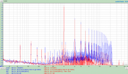
Next is the UBT-2 (5K) OPT.
As expected, the 5K transformer has lower distortion at one watt. At 4.5W it is starting to produce significant distortion, however this is expected at this operating point which is expected to be similar to 6.5W out with the 3K OPT. The higher our impedance, the lower the distortion at 1W, but also the lower the power out before clipping.
As expected, the 5K transformer has lower distortion at one watt. At 4.5W it is starting to produce significant distortion, however this is expected at this operating point which is expected to be similar to 6.5W out with the 3K OPT. The higher our impedance, the lower the distortion at 1W, but also the lower the power out before clipping.
Attachments
Listening tests were performed with a set of TangBand W5-2143s in Slot port enclosures.
Music was various albums I had digitized including Bob Dylan and Johny Cash, Billy Joel, Christopher Cross, Deep Purple, Genesis, James Taylor, Leon Redbone, Emerson Lake and Palmer, Joni Mitchell and Liquid Tension Experiment.
The best sounding transformers were the big Edcore CXSE25-8-5K. The UBT-2 placed second and didn't seem as authoritative. The UBT-3 and GXSE15-8-5K were a toss-up. The UBT seemed muddy while the GXSE seemed thin on the bottom although mid range up seemed very clear and detailed.
I will have to try this again when I get the 2A3 amp built, and possibly a 45 amp.
5K transformers are definitely an improvement over the 3K in terms of lower measureable distortion, better distortion component distribution, and listen-ability.
Attachments

I am very sceptical that those distortions are caused by the xformers. They are simply too high for even a bad xformer.
I believe you are looking at the amplifier distortion primarily.
Jan
I believe you are looking at the amplifier distortion primarily.
Jan
Thanks for the distortion graphs.
That amplifier should be fun to listen too.
I liked all my 300B amplifiers, single ended and push pull.
Did you use AC filaments, or DC filaments on the 300B tubes?
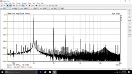
I see very small 120Hz upper and lower sidebands on each tone, 1kHz, 2kHz, 3kHz, etc.
(sideband at 880Hz, 1120Hz, on the 1k tone; and on each harmonic of the 1kHz tone).
That amplifier should be fun to listen too.
I liked all my 300B amplifiers, single ended and push pull.
Did you use AC filaments, or DC filaments on the 300B tubes?
I see very small 120Hz upper and lower sidebands on each tone, 1kHz, 2kHz, 3kHz, etc.
(sideband at 880Hz, 1120Hz, on the 1k tone; and on each harmonic of the 1kHz tone).
Filtered DC on the filaments, no regulation.
Yes, the distortion is primairly from the amp, however the transformers do have an impact. The largest impact is the change from 3K to 5K impedance and it's loading effect on the output tube.
Yes, the distortion is primairly from the amp, however the transformers do have an impact. The largest impact is the change from 3K to 5K impedance and it's loading effect on the output tube.
I do not think that the transformer introduces these distortions but the choice of its impendance and the wrong choice of the driver. I built an amplifier with 300b and the transformer has 5K/8 ohm designed and coiled by meFiltered DC on the filaments, no regulation.
Yes, the distortion is primairly from the amp, however the transformers do have an impact. The largest impact is the change from 3K to 5K impedance and it's loading effect on the output tube.
Attachments

- Home
- Amplifiers
- Tubes / Valves
- eBay 300B PC board kit