It says 0.2% distortion on the drawing but in the graphs I see about 3%.
Is that a typo on the paper?
Jan
Is that a typo on the paper?
Jan
The distortion of 0.2% refers to those produced only by the driver, obviously they are much smaller than those inserted by the final tubeIt says 0.2% distortion on the drawing but in the graphs I see about 3%.
Is that a typo on the paper?
Jan

I may go back and try the Cascode circuit again as a driver.
I found an interesting thesis from 1956 which mentions using the Cascode in audio. see page 24, Conclusion.
Cascode Thesis
My biggest concerns of the Cascode are low PSRR, high output impedance for driving the 300B input, and the fact that the 6SN7 has low Gm for the circuit.
I will breadboard the Cascode before deciding whether to mod the board. In themeantime I will move the amp back to the living room and try it with the Heresy speakers again.
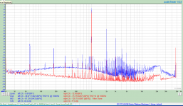
Jan, What I was trying to show was the DIFFERNECE in distortion between transformers. Look at the 4.5W scans in particular for the UBT2 fifth harmonic an up compared to the CXSE transformer. The only thing that changed was the transformers. How could the amp then be responsible?


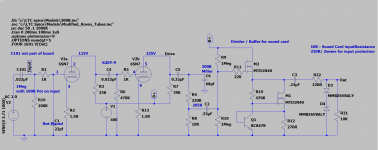
Before proceeding to try to improve the circuit I decided to add a voltage regulator. I used a simple cap multiplier with a FET as a pass element and Zener diodes for reference.
This improved the PS noise slightly, however I am using a bench power supply to drive the circuit so there may be more or less noise in the board itself.I will try to measure it later on.
This improved the PS noise slightly, however I am using a bench power supply to drive the circuit so there may be more or less noise in the board itself.I will try to measure it later on.
Attachments
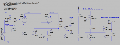
My final effort was to switch to an unbypassed cathode resistor on the lower tube to give some degenerative feedback (the 200R in series inthe original circuit did this to some degree). This gave the lowest distortion at 2.50%.
I used a 650R resistor in the Cathode of the lower tube, increased the lower resistor from 200K to 220K to increase the anode voltage, and changed the anode load of the top tube from 47K to 39K. Overall I increased the Vak of both tubes and lowered the plate load to decrease overall output resistance slightly. This gives a little better drive capability.
The 68pf cap (representing Cmiller for the 300B) had measurable effect at 20KHz where it resulted in approximately 1dB drop in the frequency response.
I will start working on the cascaded common cathode design next.
Attachments
Last edited:
With a sensitivity of 2.1Vrms for 70Vrms out, it looks to me like one could skip the input 5687.I do not think that the transformer introduces these distortions but the choice of its impendance and the wrong choice of the driver. I built an amplifier with 300b and the transformer has 5K/8 ohm designed and coiled by me
It depends on the signal source but basically you're rightWith a sensitivity of 2.1Vrms for 70Vrms out, it looks to me like one could skip the input 5687.
Blew my sound card (forgot to clamp the output of the buffer for the tube output), so I am waiting for another to arrive.
In the meantime I have wired up two sets of speakers (UBT-2 and GXSE15-8-5K) through a DPDT relay with a remote control. initially everyone could tell the difference so I looked at the outputs and found the GXSE was 1dB lower than the UBT-2.
After level balancing, it was more difficult to tell the difference, which came down to slightly less bass with the GXSE compared to the UBTs.
unfortunately life has a way of getting in the way of playing around some times. So I finally got back to the common cathode stages.
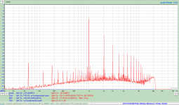
The new sound card is 116dB s/n vs the original 124dB s/n, so the noise floor is higher. That said, the distortion components are so much greater that it does not matter.
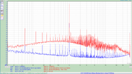
The two cascaded common cathode stages presented the lowest distortion of the tests performed so far with a THD of 1.14% per the attached plots, the red plot is the sound card in loopback for comparison.
Again the plots were with the output of the driver set to 50Vrms which should be sufficient to drive the 300B to clipping.
The new sound card is 116dB s/n vs the original 124dB s/n, so the noise floor is higher. That said, the distortion components are so much greater that it does not matter.
The two cascaded common cathode stages presented the lowest distortion of the tests performed so far with a THD of 1.14% per the attached plots, the red plot is the sound card in loopback for comparison.
Again the plots were with the output of the driver set to 50Vrms which should be sufficient to drive the 300B to clipping.
Attachments
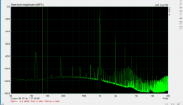
I trust arta software because I compared it to THD measured with a RADFORD distortionometer the differences being insignificantI noticed popa marius was using ARTA for analysis and I am using AudioTester 3D.
Out of curiosity, I loaded ARTA and ran it. It produces somewhat lower THD, 1.09% vs 1.14%.
What is your end goal here? Dial in the lowest overall THD? Dial in lowest THD by 300B output stage?
I gave up on the 300B for SE a while back, I found better THD in circuit at better power output and as a whole amplifier using triode connected sweep tubes like the 6AV5GA unless you went big on NFB. I'm not sure how much of the DHT hype is the THD or harmonics but in SE I don't like them. Push pull in my experience is where the 300B shines.
I gave up on the 300B for SE a while back, I found better THD in circuit at better power output and as a whole amplifier using triode connected sweep tubes like the 6AV5GA unless you went big on NFB. I'm not sure how much of the DHT hype is the THD or harmonics but in SE I don't like them. Push pull in my experience is where the 300B shines.
Comparing various proposed driver schemes to see how their THD spectrum and drive ability compared.
I finally have the time and money to investigate 300B, 2A3, 45 for myself to see what the hype is all about.
I finally have the time and money to investigate 300B, 2A3, 45 for myself to see what the hype is all about.
A 300B, 2A3, 45 amplifier that does not have negative feedback:
A two stage single ended amp (input/driver, and DHT power triode) has the following characteristic:
The second harmonic distortion of the input/driver tube stage will partially cancel the 2nd harmonic distortion of the DHT power triode tube stage.
The amount of 2nd harmonic distortion through the amp input to the amp output will vary, depending on the load line of the DHT power triode tube stage.
So, the amp 2nd harmonic distortion into an 8 Ohm load resistor will be one number at say 1 Watt out, but the amount of the 2nd harmonic distortion at the same input signal amplitude, will be different into 4 Ohm load resistor, and different into a 16 Ohm load resistor.
That is because the cancellation varies when the DHT power triode output stage's 2nd harmonic distortion varies versus the output load impedance on the output tube.
Another way to look at this is:
If the input/driver has 0.0% 2nd harmonic distortion, then the amplifier's total 2nd harmonic distortion will be the 2nd harmonic distortion of the output stage (300B, 2A3, 45).
Have fun designing, building and listening!
(I have done that for all 3 of those tube types).
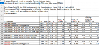
Here is the table for the tests reported in post 213. The cascaded Common Cathode with un-bypassed cathode resistors achieved the lowest distortion, and the lowest gain at 33.16 at 50Vrms out. This is not surprising since both stages have local negative feedback.
Attachments
I also tested popa marius's circuit.
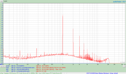
The distortion is indeed quite low for the driver with measurements of a mix of 10 6P1P and 10 6E6P (different pin-out version of the 6E5P) tubes. I got measurements between 0.118 and 0.36%thd.
The interesting thing is that the low distortion numbers are in large part due to very low 2nd harmonic content. Equal to or below 3rd harmonic level.
I expect this allows the major harmonics of the output to be from the output tube itself since there will be little 2nd harmonic cancellation.
The test included the 5687WB driver tube since without it, my sound card could not drive the output to 50Vrms.
Attachments
- Home
- Amplifiers
- Tubes / Valves
- eBay 300B PC board kit