The resistors are 5W rated, each for a total of 10W.
That puts dissipation at 42% spec, which against normal design practices of 60% deraeting is conservative.
They are mounted about 7mm off the board to allow air circulation.
That puts dissipation at 42% spec, which against normal design practices of 60% deraeting is conservative.
They are mounted about 7mm off the board to allow air circulation.
For example Yageo 5W wirewound ("lump sugar" cement resistor) at 45% rated load has 100 C temperature rising over ambient temperature!!!
Ok, so I repaired the burnt cathode resistors , put the board back to the original configuration and verified it was operating properly. (I had been making some mods.)
I then tried measuring the max output and could not get much over a watt an a half! One watt is a lot for my speakers (96dB/W-M), so I can see I would not hear this without really turning up the volume.
Unfortunately, I did not get screenshots of my previous measurements of the drive to the 300B, but went back and repeated the measurement and was surprised that the grid drive clipped well before it reached the 300B Grid bias (70V negative wrt the cathode).
So, Stephe’s predictions hold true.
So what did I do wrong in my calculations? The gain structure is valid, I made no error there.
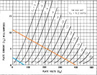
The problem lies in the my load lines in post 103 (First attached here). The upper curve for the driver stage is based on the Va, NOT Vak as it should be.
The corrected load line shows the issue. There is less than a volt of bias on the tube. It will clip due to grid drive clipping well before it can generate enough drive for the 300B.
I then tried measuring the max output and could not get much over a watt an a half! One watt is a lot for my speakers (96dB/W-M), so I can see I would not hear this without really turning up the volume.
Unfortunately, I did not get screenshots of my previous measurements of the drive to the 300B, but went back and repeated the measurement and was surprised that the grid drive clipped well before it reached the 300B Grid bias (70V negative wrt the cathode).
So, Stephe’s predictions hold true.
So what did I do wrong in my calculations? The gain structure is valid, I made no error there.
The problem lies in the my load lines in post 103 (First attached here). The upper curve for the driver stage is based on the Va, NOT Vak as it should be.
The corrected load line shows the issue. There is less than a volt of bias on the tube. It will clip due to grid drive clipping well before it can generate enough drive for the 300B.
Attachments
All is not lost however, the solution is along the lines of the schematic in post 8.
Convert the second stage to a capacitively coupled common cathode stage with an un-bypassed 1.5K cathode resistor, 39K anode resistor.
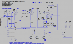
The attached schematic shows the current design.
A coupling cap is added between the anode of stage 1 and the 1K grid resistor of the second stage. A 470K grid resistor is added from the cap to 1K grid resistor junction to ground. The cathode resistor is changed from 15K to 1.5K. The Anode Resistor is changed from 22K to 39K.
The first gain stage cathode resistor is changed from 750R to 1.5K as well.
R14 on my schematic is changed from 68K to 47K to give more headroom.
Convert the second stage to a capacitively coupled common cathode stage with an un-bypassed 1.5K cathode resistor, 39K anode resistor.
The attached schematic shows the current design.
A coupling cap is added between the anode of stage 1 and the 1K grid resistor of the second stage. A 470K grid resistor is added from the cap to 1K grid resistor junction to ground. The cathode resistor is changed from 15K to 1.5K. The Anode Resistor is changed from 22K to 39K.
The first gain stage cathode resistor is changed from 750R to 1.5K as well.
R14 on my schematic is changed from 68K to 47K to give more headroom.
Attachments
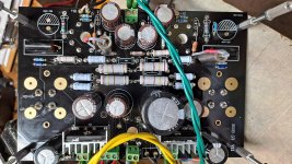
Here is a shot of the board with mods.
I used 0.022 uF K40Y-9 1KV capacitors between the stages.
I used 0.022 uF K40Y-9 1KV capacitors between the stages.
Attachments
Last edited:
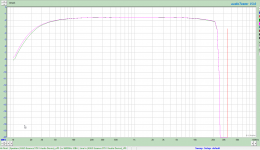
Here is the FR at 8W out. Probably better than 20Hz to 30KHz -3dB.
Attachments
Last edited:
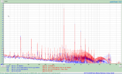
And the distortion at 1W.
One thing to keep in mind is that I am using a resistive divider to prevent overloading my sound card.
One thing to keep in mind is that I am using a resistive divider to prevent overloading my sound card.
Attachments
Last edited:
I think you will find a cascode has less roll off on the bottom end of the frequency range. At least that's what I have found. Glad you got something working for ya though 🙂
I will give that a try on my second board build.
There are two errors in the schematic in post 124 (1) R19, 3.3K is changed to 5.1K, to set Ik = 60mA, and (2) I am now using the XPWR002 Edcor transformer which gives 100V higher B+.
There are two errors in the schematic in post 124 (1) R19, 3.3K is changed to 5.1K, to set Ik = 60mA, and (2) I am now using the XPWR002 Edcor transformer which gives 100V higher B+.
Last edited:
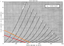
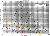
Certainly. Look at the WE 300B Datasheet, page 4. It lists combinations of OPT impedance with respect to Vak and Ia.
I am running a 3K transformer with almost 350Vak, so fourth line down in the 350V group. I should get about 8W out according to WE, and that is what I measured at about 10% distortion.
When I ran a bit over 250Vak, I got less than 4W.
http://tubebooks.org/tubedata/we300a_b.pdf
I am running a 3K transformer with almost 350Vak, so fourth line down in the 350V group. I should get about 8W out according to WE, and that is what I measured at about 10% distortion.
When I ran a bit over 250Vak, I got less than 4W.
http://tubebooks.org/tubedata/we300a_b.pdf
I don't have any info about my PP so I just do TE experiment to see if sound is different but really can't tell any. Since the highest volume my ears can handle is 1/3 and it is pretty loud. So I decide to stay at -74 to keep the tubes cool at 150F.
358v, -74, 65mA around 16w
and up to
350v, -70, 80mA, 20w
Did you crank up all the way to the max? 🙂
358v, -74, 65mA around 16w
and up to
350v, -70, 80mA, 20w
Did you crank up all the way to the max? 🙂
I don't have any info about my PP so I just do TE experiment to see if sound is different but really can't tell any. Since the highest volume my ears can handle is 1/3 and it is pretty loud. So I decide to stay at -74 to keep the tubes cool at 150F.
358v, -74, 65mA around 16w
and up to
350v, -70, 80mA, 20w
Did you crank up all the way to the max? 🙂
Are you talking about V across the tube or referenced to ground?
I'm running mine at 435V plate referenced to ground with 67V at the cathode. Which is 368V across the tube @ 76mA and 28W.
The PT on mine is kinda odd unless I change a new one.
PT: 0-10-290-310-414 at 110v primary
So it was at 310v where I run at 115v in to get 320vAC
Plate: 358v
Grid: -74v
Cathode: 65mA
I did make a measurement of OPT V drop and current where it shows around 62-65mA
At 320v AC, the B+ is around 350-358v depend on adjusting bias. Because it has SS diode so at 404v AC at 110v input, it would raise B+ to 485v. I tried first RC network at 150 ohm, it dropped down to 475v. Is there limit for first RC such as 1.2k ohm in order to get it drops down to 400v? If I can do RC LC like that, then B+ would be around 400v. I have never seen anyone running first RC that high so I haven't tried. So far the setting right now has no problem but I love to try 400v at B+ if it allow to run RC(1.2k ohm) LC
I should get about 8W out according to WE, and that is what I measured at about 10% distortion.
It's horrible.
Are you sure that this distortion due to power tube?
This measuring is in my 300B amp.
2013.01.01: comparing EH300B and EH300B gold grid.
EH300B (-81.0V, 70.0mA, 384V)
EH300Bgg (-78.2V, 70.0mA, 385V),
D3a CCS loaded, source follower driving, fixed bias, 5k:8 OPT, B+: 394V.
PWR L_THD R_THD L_Ug THD R_Ug THD
8W 1.52% 1.37% 0.43% 0.45%
Here is the FR at 8W out. Probably better than 20Hz to 30KHz -3dB.
If you change the first coupling capacitor from 22n to 220n, the lower 3dB goes down.
The 0.22nf Cap is only in the simulation. The note on the schematic explains "C101 is not part of board".
My Vak is 358 vs your 385, so all things else being equal, my distortion will be much higher than yours at 8W out. At 8W out and my bias point, I am in hard clipping.
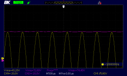
the first screenshot is the grid drive and cathode voltage at 7Vrms out (6.125W) into an 8 ohm load resistor. As you can see, It is about to go into grid current draw. So at 8W out my distortion is high.
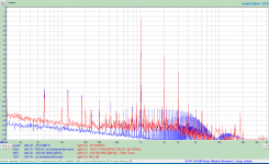
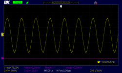
The second shot is grid drive at max with the output tube removed (220V p-p) with Vin = 0.960Vrms showing there is no issue with the input and driver stages.
My Vak is 358 vs your 385, so all things else being equal, my distortion will be much higher than yours at 8W out. At 8W out and my bias point, I am in hard clipping.
the first screenshot is the grid drive and cathode voltage at 7Vrms out (6.125W) into an 8 ohm load resistor. As you can see, It is about to go into grid current draw. So at 8W out my distortion is high.
The second shot is grid drive at max with the output tube removed (220V p-p) with Vin = 0.960Vrms showing there is no issue with the input and driver stages.
Attachments
So at 8W out my distortion is high.
So where does the distortion level climb past 1% or whatever the point is where it turns upward?
And the fact the driver can swing the voltage with no load doesn't mean anything. It's like measuring the no load voltage of a transformer, what matters is what is it when driving into the intended load.
Last edited:
- Home
- Amplifiers
- Tubes / Valves
- eBay 300B PC board kit