Hi François,[...] Reportedly EL84 performs best in Ultralinear configuration with an UL ratio of 23%. Toroidy transformers typically have 40% UL taps, but they can provide these with 23% ratio at a nominal fee.
Could you tell me more about this Ultralinear concept? What are this percent values about?
Cheers,
Jacques

Thanks for posting the Rodenhuis book! I have it on my shelf but had not looked at it recently. Nice explanation of UL operation starting on page 7.
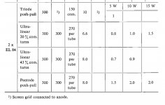
Interesting that Rodenhuis found that PP EL84 pair with 270 volts produces 10 watts into 6.6k UL 20% at 1% distortion, while it makes 10 watts into 8k UL 43% at 0.9%. Wonder what the figures are for these transformers with plate voltage at the more typical 300 volts.
Zintolo, could you please remind us of your experimental findings with 23% UL Toroidy transformers vs 40% UL?
Attachments
I usually build my amps on a Hammond 1441-32BK3. The top and bottom cost me about 60$ at a1parts...
kodabmx, I see that you have lots of experience in this field, please PM me if you're interested in selling some matched parts. It will not let me start a conversation yet.
Hi Francois,
I've done some tests at 23 and 40% UL at 8kOhm Raa with a B+ around 340V, together with other feedback.
If you plan to use UL alone, I'd suggest to use 40% UL, whilst if you plan to implement other feedback systems I'd go towards 20% and keep the load at 8k (my preference): 6k6 squeezes few watts more, but the overall sound is worst, so no reason to do it.
I have to say that I really like how EL84-based amps sound, both in Hi-Fi and guitar amps as well.
It's a tube easy to drive with a very euphonic midrange, and power enough to drive efficient speakers into loud territories.
I should have shortly a pair of Frugal Horn XL with Mark Audio 11MS and will then have a pair of Silbury with Mark Audio 10.3.
At the moment I test my amps mainly on a pair of Klipsch RF82 and I like them alot.
I will do some tests on another kind of feedback as soon as I'll be able to enter the new house, where I'll be able to make further tests, better measurements and some noise.
Francois,
Please see my additions to the chart in post 84. The first two columns are volts. The third column is cathode resistor per tube. Yes, for a 20% UL tap you get less more power but also more distortion. It's interesting that almost all guitar amps run pentode mode. Pentode, from graphs I've seen, have a more straight-line distortion curve, distortion vs power. Maybe that's what guitar players like.
I couldn't open the link in post 82, my antivirus software was being over-protective. I believe this is the same or similar book to The Mullard "Tube Circuits for Audio Amplifiers". Search the web, someone has scanned it and it's available as a PDF. If you can locate it check out the Ten-watt EL84 Amplifier in chapter six. Not to give you any more options, but read the section on Low Loading. Essentially you run the tubes cooler (bias wise) into a lower impedance transformer. The sustained output power is less but the short-term power is equivalent to a "normal" loading. I haven't tried this but if someone already has some 6K primary transformers it might be worth a try. At any rate, running the tubes cooler, bias-wise, might prolong their lives. Not a bad thing with the state of tube availability recently.
Steve
Attachments
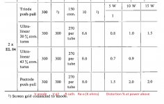
Steve, you are correct regarding voltages! Sorry, my mind wandered on the anode voltage. What got me off track was actually puzzling why Rodenhuis did not have an entry for UL43% distortion at a power output of 15 watts. Perhaps you can’t get 15 watts under those conditions.
43% Ultra Linear negative feedback is only 7 dB away from Triode Wired. And Triode Wired is by far the lowest power mode.
Getting 15 Watts from push pull EL84s and 43% UL, if at all possible, will have very high distortion at that power level.
Getting 15 Watts from push pull EL84s and 43% UL, if at all possible, will have very high distortion at that power level.
Dave Gillespie measured 18.9 watts at 0.12% (@ 1kHz) with his EFB bias modification for Dyna SCA35. However, Dyna puts about 340 V across the EL84 anode to cathode. See fig. 3 here: http://www.tronola.com/A_New_Look_At_An_Old_Friend.pdf
Last edited:
I've seen the Gillespie article and what bothers me is that like the Dynaco it's based on all of the EL84 cathodes are connected together. Unless the tubes match and age perfectly unbalanced DC conditions could result in the output transformer(s). I prefer to individually bias the tubes using the DIYtube.com method I showed in post 20. It has worked well for me on a couple of builds, Just my 2 cents.
So far, since 2006, the EL84 amp that I built, and later modded with Gillespie's bias method has never given me problems, and I get around 17 watts/ch before clipping.
I used an old Magnavox 93 series chassis and it's PT and choke, but everything else is my design.
Seductive and accurate amp it is!

I used an old Magnavox 93 series chassis and it's PT and choke, but everything else is my design.
Seductive and accurate amp it is!
Steve,I've seen the Gillespie article and what bothers me is that like the Dynaco it's based on all of the EL84 cathodes are connected together. Unless the tubes match and age perfectly unbalanced DC conditions could result in the output transformer(s). I prefer to individually bias the tubes using the DIYtube.com method I showed in post 20. It has worked well for me on a couple of builds, Just my 2 cents.
Good point! However, even if you bias individual power tubes AT the quiescent point of operation, can you be sure in a PP pair their curves match all the way up to maximum power? I think not. So, I think it is a bit academic to fret too much over individual bias, vs matched pairs and quads.
I rebuilt my Dyna SCA35 as per mr. Gillespie design, and with a matched quad it performed flawlessly, as attested to by wiseoldtech above. Recently the new amps I built, I must admit, featured individual bias 😁
Last edited:
My cathode biased 6P43P (similar to EL86 I think) is triode connected, and I use an LM317 bypassed with 1000µF per cathode on it. It gives about 10 watts/channel. My other cathode biased amp's output stage is a textbook GEC KT88 example with 600R per cathode each bypassed by 470µF, 560V B+ and it can make over 60W as ultra linear, and about 30W as triode, but it would make 100W if I was using fixed bias according to the datasheet 🙂
Lately all of my amps have been designed using the AB-4 (or AB-Q but I don't like it as much) autobias module from Pavel at audioamp.eu
Lately all of my amps have been designed using the AB-4 (or AB-Q but I don't like it as much) autobias module from Pavel at audioamp.eu
If OP would allow a quick digression, I would like to ask why you favor Pavel’s AB-4 over the AB-Q? I have a Q waiting to go to work.
I find the AB-4 works better, especially for my designs that can idle at 100mA but peak almost 1A. The AB-Q starts walking the bias around on loud music but the AB-4 doesn't seem to. The fact the AB-4 uses external cathode resistors is also nice, as I use 5W parts. AB-Q will usually be destroyed by a tube arc-over. AB-4 usually continues to work, and if not change the jfet opamps. Pavel even puts DIP8 opamps in sockets for me now. 🙂
Just watch out for the 25V 100µF caps on either one. I've had them dry out but replacing them with better parts (>10000H, 105°C) fixes that.
In fairness though, I run the boards in a sealed amp chassis that can hit 70°C and most people ventilate their designs. Mine are ugly with vent holes so I design them to run hot.
One nice thing about AB-Q is the 6V is tied to ground (pin closest to the middle of the board) so you can use an existing heater transformer if it's NOT CENTRE TAPPED. The AB-4 REQUIRES a floating 6 to 12VAC supply because it uses a voltage doubler for it's power.
No problem 🙂 I am learning quite a bit in this thread !If OP would allow a quick digression, I would like to ask why you favor Pavel’s AB-4 over the AB-Q? I have a Q waiting to go to work.
I should add that I'm not trying to slag the AB-Q by any means... I used one in a modular amp I built for a guy who's been using it everyday for a year without any problems. In that case the amp uses 320V B+, biased at 60mA, peak currents around 300mA and easily manageable for the AB-Q 🙂
Also, the AB-Q doesn't use JFETs so it's a little less sensitive. I had a leaky soldering iron blow up the JFETs on an AB-4 before (hence the sockets)...
Also, the AB-Q doesn't use JFETs so it's a little less sensitive. I had a leaky soldering iron blow up the JFETs on an AB-4 before (hence the sockets)...
- Home
- Amplifiers
- Tubes / Valves
- Easy DIY tube amp