Tell them you want one a lot like their TTG-EL84PP except you want 6.8K P to P.
no. 7 : Toroidy don't specify the UL taping ratio so it's anything you want between say 20% to 43%, Your choice based on what you fancy reading through the previous posts on this thread.
Post schematic of the little bear if you have it. Chances are you can find something from Hammond or Antek that will do the trick. Is the little bear a headphone amp?
Toroidy does specify the UL ratio of the standard trafos and it is 43%.
https://sklep.toroidy.pl/en_US/p/TT...sformer-8kOhm-2xEL84-Push-pull-or-similar/561
https://sklep.toroidy.pl/en_US/p/TT...sformer-8kOhm-2xEL84-Push-pull-or-similar/561
I'm guessing the little bear is a line or phono stage? Try this one: https://www.antekinc.com/as-05tc200-50va-200vx2-transformer/
Connect the two 200volt secondaries in parallel for the B+. Use one 6.3 volt winding for the 12AX7s and the other for the rectifier.
S.
Connect the two 200volt secondaries in parallel for the B+. Use one 6.3 volt winding for the 12AX7s and the other for the rectifier.
S.
Tell them you want one a lot like their TTG-EL84PP except you want 6.8K P to P.
Post schematic of the little bear if you have it. Chances are you can find something from Hammond or Antek that will do the trick. Is the little bear a headphone amp?
6.8K Being the primary impedance or what? Tubelab specifies 7.6k, maybe I need to do some more research on this.
I'll attach the schematic for the t10 which is still the same. It's a phono preamp. It uses a 200-0-200v, 15v, and a 6.3v.
Thanks
I should include that one of the reasons for me getting a custom PT for it is that it was built for 110v and after reading a very long post about the Little Bear people are reporting heater voltages at +12-13%. My line voltage here is 123v so I would like to get it right before I install my genalex's just in case it reduces tube life. I would like to make a bucking transformer in the meantime, has anyone here ever made one from a computer power supply transformer? (Just an idea i got while watching blueglow's youtube video on bucking transformers. I happen to have 2 old atx psu's lying around that will never get used.) Let me know if I'm getting too off topic and I'll start a new thread.
Attachments
Last edited:
This from the Tubelab.com site:
The SPP is a push pull amplifier. The output transformer must be designed to work in a push pull amplifier. The ideal primary impedance for this design is 7.6 K ohms. Impedances from 6.6 K ohms to 8 K ohms have been tested and work well.
If I were you I wouldn't go to the trouble of a custom trans.
Link: Scroll about half way down the page. http://tubelab.com/designs/tubelab-spp/applications/.
All you need to do with your little bear is put a resistor between capacitors C1 and C2, negative side. Use ohms law to figure it out. The tubes will draw about 0.9 amps.
+1 what Steve said. A standard Toroidy TTG-EL84P with 8k primary and UL43% will work very well with the SPP circuit, but the choice is your.If I were you I wouldn't go to the trouble of a custom trans.
In the US the least expensive way to buy a Toroidy TTG-EL84PP is from TME.com. They sell them for US$66.32 each and ship them from Poland for $9.90 for each transformer (last time I checked shipping). I have purchased several pairs of outputs and they all reached me within 5 business day in central USA. I see TME online shows only 1 in stock now, but expect more in mid May, so check that out.
https://www.tme.com/us/en-us/details/ttg-el84pp/toroidal-transformers/toroidy/
All you need to do with your little bear is put a resistor between capacitors C1 and C2, negative side. Use ohms law to figure it out. The tubes will draw about 0.9 amps.
Thanks Steve, will do. I asked why not do this on the huge Little Bear thread a while back and haven't got an answer yet, so now I can move on.
Yes, I'm very familiar with that Tubelab SPP page, haha. You just threw me off with the 6.8k and I saw their 8k OT's, I've just been taking everything very literally such as the 7.6k and the OT being the "most critical component in any tube amplifier."
My OPTs are toroids, not sure how to calculate a right angle between them and the PT 🤓 .
Greetings Jacques, and cheers to getting the iron hot and valvewizard (insert rabbit hole.) I thought the same thing and it can be oriented at a right angle, but I don't think that's how it was intended (or should we explore this?)
Steve, if you turned it 90 degrees like in the picture it would still be in a circle and the windings would have gone around that circle 360 degrees and/or balance each other if I remember correctly.
Thanks dudes, I'm gonna try to get some sleep, do more research and repeat.
Here's a couple of links. If you sift through part 2 and 3, you'll find several EL84, 6V6, and 6AS7/6080 amps.Hi Folks,
After building many solid state amps, I'd like to try building a ~10W tube amp (mains 230V).
Possibly with easy to find transformers and tubes.
Any recommended schematics, links or maybe kits available?
Thanks,
Jacques
http://lilienthalengineering.com/100-amplifiers-chapter-1/100-amplifiers-part-2-1945-54
http://lilienthalengineering.com/100-amplifiers-chapter-1/100-amplifiers-part-3
It is possible to get inexpensive transformers for 10W output
https://www.tubesandmore.com/products/transformers_chokes?filters=740a741c65a740
HEADS-UP FOLKS
Parts Connexion (no connection) has a 20% off sale going this weekend. Get your EL84s, 5AR4/GZ34s and 12AT7s while you can.
S.
Parts Connexion (no connection) has a 20% off sale going this weekend. Get your EL84s, 5AR4/GZ34s and 12AT7s while you can.
S.

Jacques,
Depending on your B+ voltage the dissipation on the EL84s might run a bit hot with 270 ohm cathode resistors. Tubes being more difficult to procure these days......
S.
Depending on your B+ voltage the dissipation on the EL84s might run a bit hot with 270 ohm cathode resistors. Tubes being more difficult to procure these days......
S.
Transformers for low-cost build:
Just putting it out there...
If anyone is siting on the fence because of the transformer cost of an SPP build these might make it possible.
If you are living in the USA one good, reliable and reasonably priced supplier for trannies is Antek. Also IF you are content with solid state rectification these might just do the trick and you'll only be spending about 150 bucks (!!!) on "iron'.
Power trans ($52): https://www.antekinc.com/as-2t250-200va-250v-tube-transformer/
Output trans ($44 each): https://www.antekinc.com/mp-10w80-audio-output-transformer/
The output trannie above is only rated at 10 watts but should work fine.
Alternatively these ($72 each) are rated for 25 watts and will still keep the total iron budged below 200 bucks:
https://www.antekinc.com/mp-25w76-25w-output-transformer/
Cheers, S.
Have you used or heard these Antek output toroids? If so could you tell more, please. Initially the datasheets showed response curves that did not impress, but I see they look quite nice now. Perhaps there was a problem with the measurements rather than the transformers.
I have used several of Antek‘s power transformers and have been very satisfied.
I have used several of Antek‘s power transformers and have been very satisfied.
I've used the power ones too and they seem quite good. I haven't used the OPTs but a few on the forum have tried them and found that they measured OK. The frequency response curves on the bigger push-pull OPTs look to have some nasty stuff and/or roll off at higher frequencies but the lower power, 40 watts and less, look to have decent response and might be worth a try. The 30 watt SE transformers look to a bit suspect.
At ~50 to 70 bucks a piece it's very tempting to try them for a low power amp like an EL84.
At ~50 to 70 bucks a piece it's very tempting to try them for a low power amp like an EL84.
Jacques,
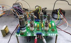
Good for you! The good thing about getting it running before it's in a chassis is you can experiment VERY, VERY, VERY carefully with transformer and choke positions to determine their best orientation for minimum hum induction. No test instruments required!
This seems like a very long procedure but trust me, it takes longer to read about than it actually does to perform.
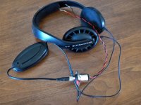
I use a cheap pair of headphones (see picture) meant for use with mobile devices and an adapter. They don't sound very good but have low impedance and are very sensitive as required by mobile devices.
Unplug your amp, let the capacitors discharge and replace the input jack connections with shorting links.
Before you start it's best if you twist all of the leads between the transformers and the board. This will help minimize radiated AC fields. Do these in pairs, 6.3 volt filament pair, 5 volt filament pair, high voltage pair. Also twist the choke pair.
Connect the amp signal ground. I used the connection in the middle of the input jack connector, to the ground on the AC inlet. This is necessary because leaving this connection off might give hum or noise that will mask what you are trying minimize with transformer position.
Use electrical tape to anchor the posts supporting the board to your work surface. This will prevent the board moving while you are experimenting.
It's best to load the output transformers with a resistor, anything between say, 5 and 25 ohms. 1/2 or 1 watt resistors are fine or you could just connect a speaker.
Arrange your transformers and choke in the position you plan in the chassis.
BE REALLY CAREFUL BECAUSE YOU WILL BE POWERING UP THE AMP AND YOU DON'T WANT TO ZAP YOURSELF.
Power the amp and let it warm up for a minute or two.
One possible source of hum is a large DC imbalance in the OP transformers. You can check this by measuring the voltage across the EL84 cathode resistors R112 and R116 of one channel and R212 and R216 of the other. Ideally, the voltage of each channel pair should be nearly identical. Swap around tubes to get the best matching pair in each channel if necessary.
Carefully touch the wires connected to the headphones to the speaker terminals of the channel closest to the power transformer. Ideally you should not hear any hum but there is almost always a little. A very faint hum in sensitive headphones will be totally inaudible when connected to speakers. A faint hiss might be heard but is nothing to worry about.
The power supply choke can often, in my experience, be the cause/source of hum.
If you work very, very carefully you can change the choke's position and orientation while the amp is running. (Wearing a heavy pair of rubber gloves should give you a bit of a safety factor.)
You may also experiment with the power transformer position and orientation as this might affect the output transformers. Since the OPTs are toroids their orientation shouldn't matter. Just keeping them as far as possible from the power trans should help.
Good luck and don't electrocute yourself!
Good for you! The good thing about getting it running before it's in a chassis is you can experiment VERY, VERY, VERY carefully with transformer and choke positions to determine their best orientation for minimum hum induction. No test instruments required!
This seems like a very long procedure but trust me, it takes longer to read about than it actually does to perform.
I use a cheap pair of headphones (see picture) meant for use with mobile devices and an adapter. They don't sound very good but have low impedance and are very sensitive as required by mobile devices.
Unplug your amp, let the capacitors discharge and replace the input jack connections with shorting links.
Before you start it's best if you twist all of the leads between the transformers and the board. This will help minimize radiated AC fields. Do these in pairs, 6.3 volt filament pair, 5 volt filament pair, high voltage pair. Also twist the choke pair.
Connect the amp signal ground. I used the connection in the middle of the input jack connector, to the ground on the AC inlet. This is necessary because leaving this connection off might give hum or noise that will mask what you are trying minimize with transformer position.
Use electrical tape to anchor the posts supporting the board to your work surface. This will prevent the board moving while you are experimenting.
It's best to load the output transformers with a resistor, anything between say, 5 and 25 ohms. 1/2 or 1 watt resistors are fine or you could just connect a speaker.
Arrange your transformers and choke in the position you plan in the chassis.
BE REALLY CAREFUL BECAUSE YOU WILL BE POWERING UP THE AMP AND YOU DON'T WANT TO ZAP YOURSELF.
Power the amp and let it warm up for a minute or two.
One possible source of hum is a large DC imbalance in the OP transformers. You can check this by measuring the voltage across the EL84 cathode resistors R112 and R116 of one channel and R212 and R216 of the other. Ideally, the voltage of each channel pair should be nearly identical. Swap around tubes to get the best matching pair in each channel if necessary.
Carefully touch the wires connected to the headphones to the speaker terminals of the channel closest to the power transformer. Ideally you should not hear any hum but there is almost always a little. A very faint hum in sensitive headphones will be totally inaudible when connected to speakers. A faint hiss might be heard but is nothing to worry about.
The power supply choke can often, in my experience, be the cause/source of hum.
If you work very, very carefully you can change the choke's position and orientation while the amp is running. (Wearing a heavy pair of rubber gloves should give you a bit of a safety factor.)
You may also experiment with the power transformer position and orientation as this might affect the output transformers. Since the OPTs are toroids their orientation shouldn't matter. Just keeping them as far as possible from the power trans should help.
Good luck and don't electrocute yourself!
Attachments
Thanks Steve for the advice. The chassis is on its way and will try that.
I have ne audible hum at the moment: without signal, I cannot tell whether the amp is on or not.
While playing, I do have a slight imbalance though, in favor of the left channel. Swapping the ECC81's did not help. The EL84's are matched quadruples.
I wonder If I could tweak some resistor value on the board (maybe replace R105/205 with a trimpot ?) to correct that (I prefer not to use input pots).
Changing the value of R105/205 will not affect gain. What I suggest you do is measure and record the DC voltages at all pins on every tube (don't bother with the filaments). Compare the measured voltages for each channel, they should be with 10%. A difference could be down to a tube or perhaps a wrong resistor value.
- Home
- Amplifiers
- Tubes / Valves
- Easy DIY tube amp