but I insist, a PA amp chassis (broken down or not) in 2U is very good as a base and you can find it for 50/100€ on the net.
The problem these days is the cost of the raw material.
I built two amps with Dibond, it's very practical and easy to find, look on the net
The problem these days is the cost of the raw material.
I built two amps with Dibond, it's very practical and easy to find, look on the net
Stonegreen,
Your schematic looks about right. The reason I used a double (or triple) pole switch is it provides a place to mount the inrush limiter and connect wires to it so I didn't have buy and mount a terminal strip.
Of peripheral interest perhaps, Updating old output transformers with new Hammonds: https://wallofsound.ca/audioreviews/amplification/what-difference-does-an-output-transformer-make/
Above also includes a YouTube link to an incredible music performance.
S.
I usually build my amps on a Hammond 1441-32BK3. The top and bottom cost me about 60$ at a1parts...
It looks good but made out of steel: it is kind of hard to work with...I usually build my amps on a Hammond 1441-32BK3. The top and bottom cost me about 60$ at a1parts...
I read somewhere the top should be non-magnetic like alu or copper: is it true?
I thought so too, but it's really not much harder than using the aluminum version, and it's a lot stronger. Plus the black looks nice 🙂
I use titanium coated (or cobalt) bits, I use step drill bits for mid sized holes, and an electrical knockout punch for the socket holes...
Crappy tire has the step drill bits on sale this week 🙂
https://www.canadiantire.ca/en/pdp/...-0540698p.html?_br_psugg_q=step+drill+bit+set
I use this punch set with an impact driver:
https://www.amazon.ca/AMZCNC-Knockout-Electrical-Conduit-Stainless/dp/B09FJ816NX/ref=sr_1_8?keywords=knock+out+punch+tool&qid=1649516275&sprefix=knock+out,aps,66&sr=8-8
I've also built stuff in these: They cost 50$ at the local home hardware. http://www.allenclosures.com/enclosures/2U-rackmount-Chasis.htm
The issue with a Magnetic Steel chassis is the transmission of hum from both the power transformer and B+ filter choke . . .
. . to input transformers, interstage transformers, and output transformers.
Push pull output transformers are less sensitive this way versus single ended output transformers.
Interstage transformers are more sensitive to magnetic hum fields.
Input transformers are most sensitive to magnetic hum fields.
The magnetic "hum gain" is highest at the input stage, and the lowest at the output stage.
Rotating the orientation of laminations for lowest hum may help.
Spacing of power transformer and filter choke to other transformers may help (signal transformers).
These issues can be a problem even with an aluminum chassis.
If you use a magnetic steel chassis, and replace the top with aluminum or copper, then . . .
If you mount the power transformer, filter choke, and signal transformers at the outside edge of the modified chassis, then the outer steel walls will still transmit the magnetic fields from the power transformer and choke to the signal transformers.
Ground loops are another cause of hum.
Input ground loops and first B+ capacitor ground loops tend to be the most problem.
Happy designing, building, and listening!
Huggygood, could you give me the french name for that tool and where you source it?or cookie cutters, I don't know the name in English
In the US they're "chassis punches" or the electricians call them "slug busters". Just search "chassis punch". Greenlee is the big brand here. The bay or amazon has them as well as electrical supply houses.Huggygood, could you give me the french name for that tool and where you source it?
I find I don't get anymore electromagnetically coupled hum in any of my steel builds. There is one chassis that the choke turns into a speaker, but you can't hear it over the SPL, you can just feel it if you touch the bottom plate under the choke. When I did, making the chassis larger to space the coils further apart worked as well as turning the choke and PT 90° to the OPTs.
The only electromagnetically coupled hum I'd experienced was due to installing the capacitors right undert the PT.
If you want a practical example, put a C filter on a toroidal PT, check hum, then move the cap into the centre bore of the coil 🙂
The only electromagnetically coupled hum I'd experienced was due to installing the capacitors right undert the PT.
If you want a practical example, put a C filter on a toroidal PT, check hum, then move the cap into the centre bore of the coil 🙂

Steve,
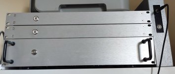
I'd like to put the heavy metal inside the chassis and only leave the tubes sticking out. I measured and it should all fit in the box.
For the tube holes I will use the tool below. What are the little decorations around your smaller tubes?
I'd like to put the heavy metal inside the chassis and only leave the tubes sticking out. I measured and it should all fit in the box.
For the tube holes I will use the tool below. What are the little decorations around your smaller tubes?
Attachments

emporte pieces evierHuggygood, could you give me the french name for that tool and where you source it?
https://www.amazon.fr/emporte-piece-evier/s?k=emporte+piece+evier
If you use a big step bit instead of a punch, make sure to clamp the work, and use a drill press, otherwise you might bind the tool and bend the chassis. Ask me how I know and why I use punches now...Steve,
I'd like to put the heavy metal inside the chassis and only leave the tubes sticking out. I measured and it should all fit in the box.
For the tube holes I will use the tool below. What are the little decorations around your smaller tubes?
Jacques,
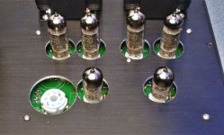
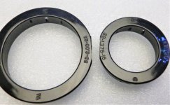
They are Heyco bushing/grommet available from Mouser. Part number 836-2210 for the 9 pin tubes, and 836-2400 for the rectifier (if used). A bigger hole is needed and they can get kind of close together on some of the tubes, see attached pictures. They can hide some of your sins if your holes in the metal are not perfect. I think I got a local tool shop to make the holes in the picture below. I had an aluminum chassis and I wanted to hide the raw metal surface.
Be careful using the tool you show in post 73. They can wander from the ideal position. Practice on some scrap metal before you make your holes in the real chassis.
Attachments
Using old chassis, and building something completely new . . .
Do not try and use a 5 Henry or 10 Henry B+ choke input filter, on a Dyna Stereo 70 (magnetic) steel chassis.
The difference is 500uV to 1,500uV when using the Dyna chassis, versus Less than 100uV on an aluminum chassis.
The different plate resistances of different output tube(s) causes the variation of the hum.
(all ground loops fixed, angular rotation of the laminations done properly, and B+ is very well filtered).
Yes, there is no global negative feedback used, so no hum reduction from global negative feedback.
And yes, all the magnetics are stood off of the steel chassis by 1/4 inch non-magnetic spacers.
Just my experience.
Last edited:
Hi, I'm also building an el84 Tubelab SPP for the first time.
Power transformer: I've been talking with toroidy about a power transformer that meets the specs and they suggested a custom one for about the same price. My line voltage is 122-123v. Should I get it built for 120v? If so, what should I shoot for as far as HV , 310 -325? I've read that some get 300-0-300 and then get the correct voltage, I'm assuming this is because they're built for 115v? I'm thinking of bumping my specs to 230ma, would that be plenty or a little excessive? Thanks for recent thread btw, I've realized I should go ahead and get a choke from them as well, 1.5H 200mA? I'm using a 5u4g for the rectifier.
Chassis: I was planning of building an all wood chassis, but am open to wood/aluminum. How much aluminum is necessary and where does it need to be if I'm just gonna line parts of it?
Pairing components: Which parts would be most important to use the 1% resistors on? I read recently that someone buys 10 of certain parts and perfectly matches them, I am not planning on doing this across the board but would if some were more effective. I accidently bought 8 el84's. Should I just break them all in and then have them re-matched?
I am planning on paying a local expert to help me fine tune and show me some things.
What are you guys' thoughts on toroidal OPT's for this build?
Thanks for all of the guidance.
A 120 volt primary will likely be fine. Using a CL-90 inrush limiter will drop about a volt once warmed up and provide a soft start function. Since you are using a 5U4 you'll likely have a bit more voltage drop compared to 5AR4/GZ34. A 300-0-300 HT secondary should be OK. You don't need more than 300 volts DC and much more probably isn't good for the EL84s. Their data sheet limit is 300 volts but a bit more (310 to 320) doesn't typically bother them. A 230mA rated HT secondary? that should be fine. A 1.5H, 200mA choke worked fine for me. IT was a Hammond 156R if memory serves.
A wood frame for front back and sides with 1/8" aluminum top and bottom plates has worked for me.
No 1% resistors really need for a SPP. Often 5% resistors match to within 2% in my experience. They might deviate from nominal by more than 2% but will match each other to within 2%.
With the world tube situation because of you-know-what-country, having eight EL84s. is not a bad thing. Break 'em all in, 50 hours or so, then match them in pairs for voltage measured across the EL84 cathode resistor.
I haven't used toroids for OPTs but forum member kodabmx has and reports good results. If you are in the US this toroid might be a candidate: https://www.antekinc.com/mp-25w76-25w-output-transformer/
What are you guys' thoughts on toroidal OPT's for this build?
Thanks for all of the guidance.
If you are in Europe be sure to check Toroidy.com. Lots of Baby Huey builders used Toroidy output transformers, including me, and had all been very pleased. Those transformers test very well and provide excellent value for money. Reportedly EL84 performs best in Ultralinear configuration with an UL ratio of 23%. Toroidy transformers typically have 40% UL taps, but they can provide these with 23% ratio at a nominal fee.
Even if you are in the US, TME sells them at good price and ships them to the US for (at last count) $9.90 per transformer. Actually per <5 kg package, but the EL84 transformers are just over per pair, so, buy two individual ones. Current price US66.13. See https://www.tme.com/us/en-us/details/ttg-el84pp/toroidal-transformers/toroidy/
Last edited:

- Home
- Amplifiers
- Tubes / Valves
- Easy DIY tube amp