The increased volume at S2 caused by the baffle and the larger cone can be simmed by including a throat chamber of equivalent volume there in the sim.
No, it can't be accurately sim'ed by using a throat chamber. In this case there is no throat chamber, the divot in the cone is all part of the horn flare. If you attempt to simulate it as a throat chamber the path length won't be right. If you get the path length right there's no need to include a throat chamber because in fact there isn't one.
There's no need to make any adjustments to the path length at S2 in the sim because of the inclusion of an adapter board and a larger driver when changing a TH115 to a TH118. HornResp even includes a wizard to estimate the volume in front of the driver's cone so you can include it in the sim like I've suggested.
The extra baffle board and the deeper divot in the larger driver create few extra inches of path length. This can't be accurately simulated as a throat chamber, you have to get the path length right or the sim isn't right. Garbage in = garbage out.
As for my path length estimate "dipping only a couple of inches below the baffle board", that's pretty much where it should be when one takes the position of the driver's cone into consideration, then divides the distance between the cone and the horn's internal panel in half at that point to determine where the estimate for the path length should reside. However, even if it is off by a few inches (and I don't think it is), that's still not enough to make any significant change to Fb.
A few inches is a few inches. You were wondering how it could be tuned where the measurements suggest it is and comparing against a sim that was wildly inaccurate. If you want to know why it works the way it does you have to sim it accurately. You can't just take wrong path lengths and swap whole areas of the flare with a chamber.
I'm not even sure why we are discussing this anymore, your estimation is wildly inaccurate and in the time you've spent trying to justify it you could have completed a complex reverse engineering and Akabak sim of this cab.
I do not believe, that Hornresp simulations suit a case like this, it would be better simulated using lots of individual segments in AkAbak.
Perhaps. OTOH, it seems unusual to me that the closest you can get to a HornResp sim of the TH118 going by the horn layout provided still results in an Fb that's 26% too high (34Hz instead of 27Hz). I wouldn't have expected that huge a margin of error between sim and actual results.
In the end I side with Tom Danley: "Measurements trump simulations."
True. Maybe what we need here is an independently-done impedance measurement of the TH118 @ 2.83V. Does anyone have a spare one handy? 🙂
To be a bit more clear about the reason you can't sim the cone divot as a throat chamber - in an Od sim the throat chamber is in parallel with the horn path so the chamber can't add ANY length to the path. The path length has to be established by the flare and it has to be correct. There isn't any throat chamber in this design anyway.
The only to get the throat chamber in series with the path length would be to do an Nd sim, which would account for the path length but would still be wildly inaccurate due to the shape of the triangle section at the beginning of the flare.
It's not unusual at all because there's SEVERAL things Hornresp can't account for here (the stub, the driver taking up half the mouth, the grill and grill rails), and add to the the fact that you've miscalculated path length in the parts that Hornresp can handle and you've got a major mismatch.
Measurements only trump sims by a significant amount when sims are thrown together haphazardly. Garbage in = garbage out, and it's why people don't trust sims. I've been speaking out against this for years.
OTOH it's not a bad idea to have an independent measurement done, but I still can't understand the overwhelming reluctance to actually sim the cab properly and see what the results are. TB46 has gone about as far as you can go in Hornresp, and that isn't anywhere near far enough. This needs to be done in Akabak. And when it's done properly the sims will match the measurement unless the measurement is wrong. Like always.
The only to get the throat chamber in series with the path length would be to do an Nd sim, which would account for the path length but would still be wildly inaccurate due to the shape of the triangle section at the beginning of the flare.
Perhaps. OTOH, it seems unusual to me that the closest you can get to a HornResp sim of the TH118 going by the horn layout provided still results in an Fb that's 26% too high (34Hz instead of 27Hz). I wouldn't have expected that huge a margin of error between sim and actual results.
It's not unusual at all because there's SEVERAL things Hornresp can't account for here (the stub, the driver taking up half the mouth, the grill and grill rails), and add to the the fact that you've miscalculated path length in the parts that Hornresp can handle and you've got a major mismatch.
True. Maybe what we need here is an independently-done impedance measurement of the TH118 @ 2.83V. Does anyone have a spare one handy? 🙂
Measurements only trump sims by a significant amount when sims are thrown together haphazardly. Garbage in = garbage out, and it's why people don't trust sims. I've been speaking out against this for years.
OTOH it's not a bad idea to have an independent measurement done, but I still can't understand the overwhelming reluctance to actually sim the cab properly and see what the results are. TB46 has gone about as far as you can go in Hornresp, and that isn't anywhere near far enough. This needs to be done in Akabak. And when it's done properly the sims will match the measurement unless the measurement is wrong. Like always.
No, it can't be accurately sim'ed by using a throat chamber.
I disagree. In fact, in post #37 I did just that and showed how doing so would result in a drop in Fb, as I predicted. The equivalent of adding a few extra inches to the path length, btw 😉.
Clearly not enough.
In any Od sim the chamber is in parallel with the horn flare and can't add any length. It can add a bit of volume but that's not the same thing and won't give the same results.
Anyway, justify away, and continue to be mystified at why the sims don't match the measurements. It isn't because measurements trump sims, it's because the sims are wildly inaccurate.
Clearly not enough.
LOL, didn't you suggest that my path length estimate in that area was off by a few inches? So, now that I show you that those "few inches" can easily be accommodated by using a throat chamber estimate to cover the increased volume in that area caused by the use of an adapter board and a larger driver, those "few inches" are now not enough?
There's just no pleasing you, is there 🙂
In any Od sim the chamber is in parallel with the horn flare and can't add any length.
There is no need to. Increased volume in that area ALSO reduces Fb, which was the focus of this long discussion. The difference between choosing either approach should show up in the FR at the upper end of the TH's passband, as that's dependent on the geometry of the section in question, which obviously can't be sim'd by a throat chamber (not that HornResp's S1-S2 equivalent is that much better).
Hmm...
Maybe we need to review the approach we're taking with the HornResp sim. Perhaps treat the entire section of the horn that's directly in front of the driver as a "throat chamber", and start the horn off from the first section leading out of it.
Maybe we need to review the approach we're taking with the HornResp sim. Perhaps treat the entire section of the horn that's directly in front of the driver as a "throat chamber", and start the horn off from the first section leading out of it.
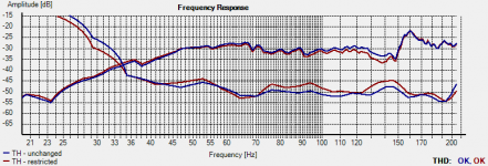
...and here's the results of a quick rough sim showing just that. In grey is the predicted response of my last sim attempt. In red is the predicted response when treating the entire section in front of the driver as a throat chamber with cross-sectional area equal to the first section of the rest of the horn, and putting S1 and S2 at the start of the horn.
Attachments
LOL, didn't you suggest that my path length estimate in that area was off by a few inches? So, now that I show you that those "few inches" can easily be accommodated by using a throat chamber estimate to cover the increased volume in that area caused by the use of an adapter board and a larger driver, those "few inches" are now not enough?
There's just no pleasing you, is there 🙂
No you can't please me by doing it wrong.
A throat chamber is not the same thing as horn path length. The effect might look vaguely similar but it's not the same, and a parallel throat chamber of equivalent volume won't tune as low as actual path length.
Hmm...
Maybe we need to review the approach we're taking with the HornResp sim. Perhaps treat the entire section of the horn that's directly in front of the driver as a "throat chamber", and start the horn off from the first section leading out of it.
I told you that isn't accurate. The triangle shape at the beginning of the horn path messes up any chance of that being accurate.
Maybe we need to review the fact that no matter how hard you try Hornresp can't sim this even remotely accurately. How are you accounting for the stub, the driver clogging up the mouth hole, the grill and the grill rails? Oh yeah, you just arbitrarily assume none of that makes any difference, lol.
At this point I've repeated myself almost a dozen times and this isn't going anywhere. Your sim doesn't come anywhere remotely close to the measurement because it isn't remotely close to accurate. Not sure how this could be any clearer. If your sim is accurate it will match the measurement if the measurement is correct. You keep trying to justify your wildly inaccurate sim and completely ignore the massive amounts of mass loading in this cab. If you simulated it right the sim would match the measurement, it's a really simple concept.
Anyway, at this point it's not worth discussing anymore. You clearly have absolutely no interest in doing an accurate sim for reasons I can't even being to imagine, so your sims are never going to match the measurement. And you will be stuck trying to figure out why it doesn't match even though I've told you several times. So I'm going to back out of this mess and you can just assume that if I had kept going I would have disagreed with just about everything you say, because you aren't saying anything new and your approach to this is dead wrong. Which is really surprising since you usually have your eye on the ball when it comes to issues of accuracy and verifying results. I'm baffled why you refuse to do a proper sim but that's life I guess.
I can absolutely guarantee that this cab is not magic and it can be very accurately simulated and the sims will match the measurements if the measurements are correct. That should be really simple common sense, I'm not sure why it's not getting through but at this point I really don't care anymore. Good luck, you're going to need it.
Last edited:
How are you accounting for the stub, the driver clogging up the mouth hole, the grill and the grill rails?
I already gave you a response concerning the likely impact of the first one based on my actual experience building and measuring THs, but you simply chose to ignore that, it seems. I've also given you a response to the impact of reducing Fb via changes in the S4 region of the horn (i.e. significant reduction in efficiency above Fb) that don't show up in the TH118's measurements, but it seems you've chosen to ignore that as well.
At this point I've repeated myself almost a dozen times
That you have. Unfortunately it does not make anything you've said any more correct. For example, you suggest that the "stub" would impact Fb. I've given you an actual example where a much, much, MUCH larger restriction in the horn at a similar location along its length only made a very small difference to Fb (in the region of 12%) and you've simply chosen to ignore that, it seems.
Concerning the "grill and rails", the impact of those is also likely to be very minor. And remember, any change in the S4-S5 region of the horn that reduces Fb will also significantly impact its performance ABOVE Fb. Ask yourself - why would Thomas Danley design a TH for PA use where the grill would have a major impact on its efficiency above Fb? Doesn't make sense now, does it?
I am still waiting to find any Hornresp or Akabak, loudspeaker sim of a tapped horn that comes anywhere close to the published manufacturers data for the Danley TH118.
I agree that some independent test data would be very welcome.
The 'cone correction' method, that I developed, was my attempt at accounting for the volume of the cone within the horn path. When the internal structure of the TH115 / TH118 first became known it was immediately apparent that the normal method of simulating fails when S2 effectively becomes zero.
The cone correction is a calculated line that replaces the line of the speaker baffle panel for the plotting out of the horn path shape.
This allows a sim to be run without using the throat chamber settings.
The throat chamber setting method still seems to be valid for simulating most speakers, but it concerns me that the compression ratio reported at S2 in Hornresp becomes erroneous when simulating a horn where the path is across the speaker cone. This has encouraged many designs where the compression ratio has probably been lower than optimal.
In case anyone starts moving sliders around in Hornresp, it becomes far more difficult to optimise a speaker once a fold has been decided on and an increase in one area has to be compensated for by a decrease in another part of the cabinet. Many tweaks to the hornshape will yield minimal changes when the overall volume is maintained.
In any Od sim the chamber is in parallel with the horn flare and can't add any length. It can add a bit of volume but that's not the same thing and won't give the same results.
Hi just a guy,
Just to clarify - throat chamber axial length is taken into account in the Hornresp OD, TH, TH1 and multiple entry horn simulation models when calculating pressures and volume velocities for the acoustical equivalent circuit. The throat chamber length Ltc is given by Vtc / Atc, and is displayed in the status bar panel at the bottom of the input parameters window when the mouse pointer is moved over either the Vtc or Atc labels or input boxes.
Kind regards,
David
I realize that, but in an Od sim the throat chamber is beside the horn flare so it can't add length to the horn flare. Brian is trying to use it to compensate for horn flare length. A small lump of volume beside a horn flare that's too short is not the same thing as having that lump of volume as a part of the flare that contributes length to the flare.
I realize that, but in an Od sim the throat chamber is beside the horn flare so it can't add length to the horn flare. Brian is trying to use it to compensate for horn flare length.
Nope - I was using it to compensate for the difference in volume between the driver's cone and that section of the horn caused by replacing the driver of the TH115 with the larger driver and adapter plate that supposedly turns it into a TH118. The end result is a small drop in Fb that's equivalent to the horn being extended a few inches. I think it's a reasonable approximation, and any differences would show up much higher in the horn's passband. You say it isn't.
Hi Y'all,
I won't have time right now to put this into AkAbak, but in AkAbak a "throat chamber" simulated as a duct may well be the way to do this.
We are coming from S3 through a number of rectangular waveguides to a transition from rectangular into a (kind of) half-moon crescent shape entry into a round duct that leads to the cone shaped driver diaphragm, we are also exiting the duct through a similar but (according to the drawing from speakerlabs) smaller crescent-shaped opening into a rectangular waveguide that (depending on how you want to look at it) terminates in a point/edge.
And all that is disregarding, that we don't know if there are any additional pieces of wood art in that area. Fun. 🙂
Finally, we don't quite know which driver was in the box when the reference measurements where taken.
But, if we beat on it long enough, maybe we'll learn something?
Regards,
Nope - I was using it to compensate for the difference in volume between the driver's cone and that section of the horn caused by replacing the driver of the TH115 with the larger driver and adapter plate that supposedly turns it into a TH118. The end result is a small drop in Fb that's equivalent to the horn being extended a few inches. I think it's a reasonable approximation, and any differences would show up much higher in the horn's passband. You say it isn't.
There's no need to use a chamber to compensate for anything, there is no chamber in this design. The chamber you are using is NOT equivalent to the horn being extended a few inches. Vaguely similar maybe but not accurate.
I wasn't going to post here anymore but had to respond to David and make it overwhelmingly clear that I still do not agree with you. At this point not simulating the cab properly is just laziness and that's the most polite term I can use to describe it. This is really surprising, you are all about accuracy usually. Justifiying fudging the sim clearly isn't working for you, you can't come even close to matching the measurements and I've told you why several times. There are several problems with your sim and it's never going to come anywhere near accurate. Comparing this to your dog food design is not an accurate parallel and all your speculating isn't getting you any closer to the answer that's pretty clearly right in front of you. A few inches here, a bit of mass loading there (and there there and there) and you drop Fb a few hz. Your sim is grossly inaccurate, just about the only thing that is vaguely accurate is the external dimensions.
This is EXACTLY why people keep saying measurements trump sims like sims are not even vaguely accurate despite being shown over and over that if the sim is accurate and the box is built accurately and a true reflection of the simulation the sims will match the measurements.
Seriously why not simulate this properly instead of making excuses and justifications? In the few hours you've spent arguing with me you could have had it mostly done.
Last edited:
We are coming from S3 through a number of rectangular waveguides to a transition from rectangular into a (kind of) half-moon crescent shape entry into a round duct that leads to the cone shaped driver diaphragm, we are also exiting the duct through a similar but (according to the drawing from speakerlabs) smaller crescent-shaped opening into a rectangular waveguide that (depending on how you want to look at it) terminates in a point/edge.
In one of the sim attempts that I did, I replaced that entire section with a throat chamber of the same csa as the new entry point into the horn. Fb dripped a little and there were only minor changes in the response curve at the upper end of the TH's usable passband. I suspect any geometric changes to this area will affect the upper passband a hell of a lot more than it would affect Fb, and in ways that don't show up in the TH115's measured response curve.
And all that is disregarding, that we don't know if there are any additional pieces of wood art in that area. Fun. 🙂
Well, there is that 🙂. Extra pieces of wood would reduce the volume of air in that area though, which may push Fb up....
Finally, we don't quite know which driver was in the box when the reference measurements where taken.
The driver's t/s parameters won't make a difference to measured Fb, which is set by the horn. The driver's physical size might "shade" S4 a bit more than a smaller driver would, but if this "shading" is in fact significant, it should also have a significant impact in the TH's upper passband, would it not? And the TH118's measured response doesn't appear to show anything of the sort.
Note that there's also the "Iron Law" to consider - when you reduce the net volume of any alignment, the efficiency at the low end is supposed to go down, not up. The published measurements show the TH118 as being equivalent to the TH115 @ around 40 Hz, and MORE sensitive at lower frequencies (up to just under 100 Hz), and both designs use 4 ohm drivers in boxes with the same external dimensions. I'll bet that if Hoffman had joined us in this discussion, he'd be very curious too about how this was achieved 🙂.
But, if we beat on it long enough, maybe we'll learn something?
LOL, and to think all of this started because I was curious as to why DIY 18" TH designs appeared to have 100 liters or more net volume than Danley's TH118 and still had higher sim'd Fbs 🙂.
There's no need to use a chamber to compensate for anything, there is no chamber in this design. The chamber you are using is NOT equivalent to the horn being extended a few inches. Vaguely similar maybe but not accurate.
I wasn't going to post here anymore but had to respond to David and make it overwhelmingly clear that I still do not agree with you.
And I don't agree with you. We will have to leave it at that. I have done some pretty intensive tests concerning how some modifications to built THs impact their response, so I'll trust my judgment on the matter for the moment.
Here's the results of a quick test I did this morning to sim the impact of placing a driver with a larger volume @ S4 in a TH. The TH in question is my POC#3 and to the sim the impact I just added a few bricks at S4 that effectively choked off about 25%~30% of the horn at that point, not including the impact of the driver itself which of course makes it quite a bit more.
Results:
1. Fb dropped by about 1 Hz (3%) and there is corresponding minor increase in response below Fb
2. Significant changes (2~3dB) at the upper end of the TH's passband (90~150 Hz). It looks in fact that a "notch" is starting to appear between 130 Hz and 140 Hz.
Which, interestingly enough, is almost exactly as I predicted 🙂
It does open up some interesting possibilities though, e.g. of easily "detuning" a TH if for a particular purpose you are willing to sacrifice several dBs at the upper end in exchange for a small increase below Fb. You can't shift Fb via DSP, but if you make a removal "step" that can be screwed into the TH at S4, you can reduce Fb a bit with little or no negative impact at lower frequencies, or at least that's what my measurements suggest.
Attachments
Last edited:
Fb dropped by about 1 Hz (3%) and there is corresponding minor increase in response below Fb
It just occurred to me that the "minor increase" below Fb might just be a measurement artifact. This measurement was a nearfield measurement of basically what is a large vent, before and after the vent's size was reduced quite a bit. Overall response may therefore need to be adjusted down a bit, to compensate for the decrease in vent size. I may have to repeat the test with some farfield measurements to determine exactly how much adjustment needs to be made.
- Status
- Not open for further replies.
- Home
- Loudspeakers
- Subwoofers
- Dual 18 Tapped Horn Design Concept