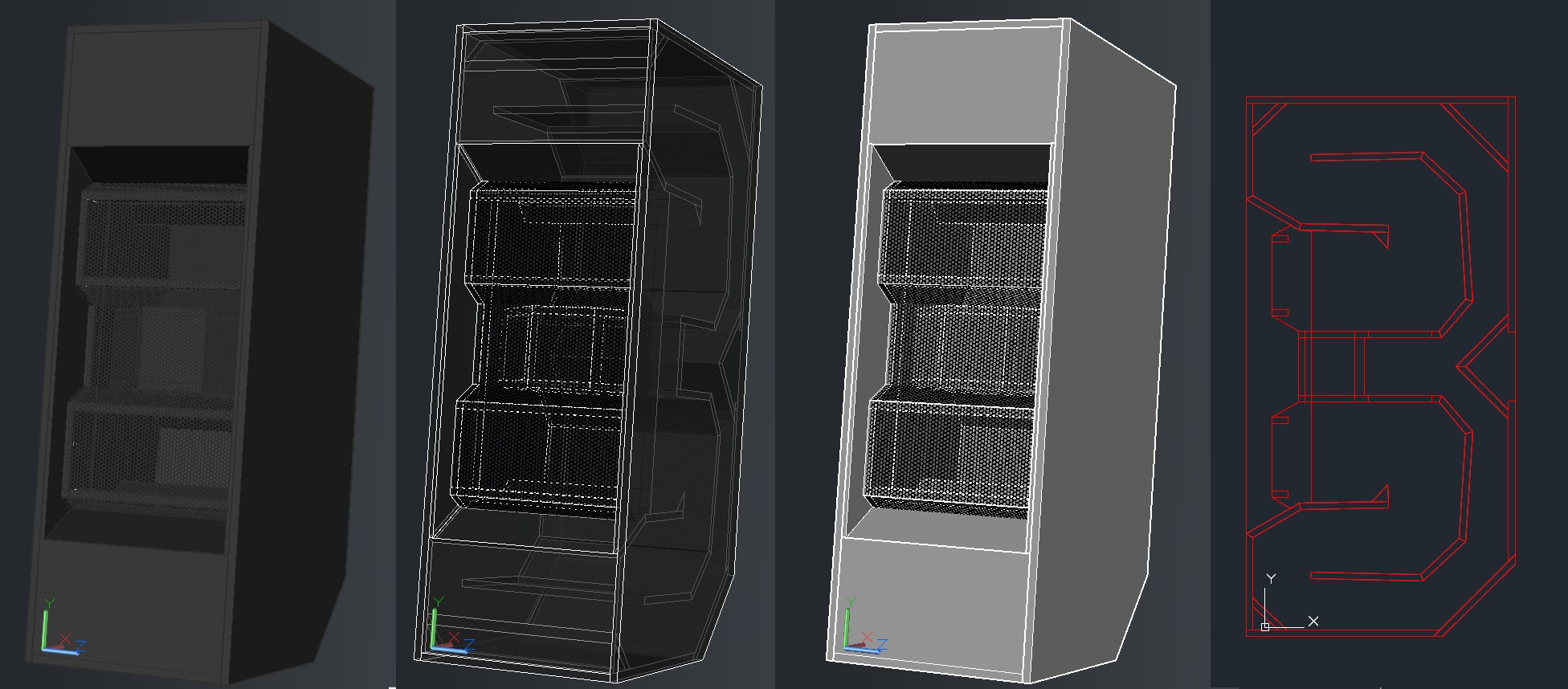
And it makes sense, the TH118 has that stub at the last bend that constricts flow, which is mass loading and path lengthening.
I'll bet that "stub" does makes little or no measurable difference to the cab's Fb. Remember my "dog food duct" mod to my first TH? See here for a reminder: The Subwoofer DIY Page v1.1 - Projects : "Proof of Concept #2". I blocked off fully 2/rds of the TH's horn at a similar point along its path with that "stub", and Fb dropped just a few Hz - from 43.7 Hz to 39 Hz. The "stub" in the TH118, if the diagram is correct (which is another thing to consider - who says that it's correct?), is significantly smaller in relation to the cross-sectional area in the TH118 TH, compared to my DFD mod. As pictured, it certainly does not block off anywhere near 2/3rds of the horn. My guess is that it's main purpose is to simply increase the length of the baffle board to accommodate an 18" driver.
Now, concerning the larger driver, another thing to note is that usually one can make gross changes to the S4-S5 segment, i.e. where the driver's mass resides, in a dual-expansion TH with only small changes to Fb. Don't believe me? Go ahead - load up HornResp with the closest TH sim, like the one I provided, and drop S4 and S5 by 25%, which IMO is much more than the impact the driver's size would have, and look at what happens to Fb when you do that. Oh, and while you're doing that, have a look at what happens to the response curve and see if it resembles the one published by TD for the TH118. There is a significant penalty to be paid in the response above Fb when decreasing S4 and S5 like that, but that's not reflected in the published FR curve for the TH118, which is supposedly 2dB MORE efficient than the TH115.
(which is another thing to consider - who says that it's correct?)
Lol, yeah, let's throw out all the data we have because it might not be 100 percent accurate. On the other hand, I can show you about 50 more drawings just like these two. They are everywhere. I'm pretty sure they are correct. People that own these cabs have participated in threads where these pics were shown and didn't mention any problems with the drawings.
Now, concerning the larger driver, another thing to note is that usually one can make gross changes to the S4-S5 segment, i.e. where the driver's mass resides, in a dual-expansion TH with only small changes to Fb. Don't believe me? Go ahead - load up HornResp with the closest TH sim, like the one I provided, and drop S4 and S5 by 25%, which IMO is much more than the impact the driver's size would have, and look at what happens to Fb when you do that. Oh, and while you're doing that, have a look at what happens to the response curve and see if it resembles the one published by TD for the TH118. There is a significant penalty to be paid in the response above Fb when decreasing S4 and S5 like that, but that's not reflected in the published FR curve for the TH118, which is supposedly 2dB MORE efficient than the TH115.
I can't do much but repeat myself at this point. The only difference between the TH115 and TH118 is the extra baffle board (including the stub) and the driver size. That's been made pretty clear by even Danley. So if that is fact, where did the 9 hz go? It's really that simple.
You are asking me to sim stuff now, you still haven't bothered to sim the plans I provided. Just making guesses based off incorrect dimensions and totally disregarding massive amounts of mass loading.
Sim the plans and if the plans were used to construct the cabs the measurements will match the sims. Like they always do.
There's no magic going on here. There's nothing in the cabs that you can't see in the drawings and the plans. You have no alternate theories about what's going on. I showed almost a couple of feet of extra path length compared to your inaccurate drawing AND a stub that both adds path length AND mass loading AND I showed an extra baffle board AND a much larger driver which both add massive amounts of mass loading. That isn't enough?
Please explain what wizardry Danley uses to drop the tuning 9 hz between these two otherwise identical cabs if it isn't the baffle board and driver size.
Last edited:
About this part specifically - you are right, the main purpose of the baffle board is to accomodate the larger driver. That doesn't mean it doesn't have a very significant effect. This isn't even close to the same thing as the dog food mod. When you did that you filled up a large volume of a small horn path with solid objects, taking away a significant amount of cab volume.
I used cans only during the testing phase, to find the best place for the restriction. In implementation, the DFD was a simple 0.5" thick restriction, as pictured at the link I provided, and the measurements I provided wrt Fb are in regards to how it was implemented. Its effect on cabinet volume is negligible.
I showed almost a couple of feet of extra path length compared to your inaccurate drawing
Your drawing shows nowhere near that gain in path length, as I've already demonstrated to you, and my modified sim is very, very close to the design pictured in that image you provided. Any differences in path length between the two will be minor, certainly not in the region of the two extra feet required to drop Fb down to ~28 Hz, and even longer if it's in fact 27 Hz. To give you an idea of how much extra path length this is, the external depth of the TH118 is 28.5" - we need to find extra path length that's almost as long at the top or bottom panel of the TH118, if the decrease in Fb is due to the path length.
AND a stub that both adds path length AND mass loading.
I've already given you access to measurements that suggest a stub of that size at that point in the horn will make little or no difference to its Fb.
AND I showed an extra baffle board AND a much larger driver which both add massive amounts of mass loading.
..and I've shown you that making even gross changes to that point in a TH where the driver resides makes only small changes in FB - the significant changes occur higher up in the frequency response curve, where you lose efficiency.
Please explain what wizardry Danley uses to drop the tuning 9 hz between these two otherwise identical cabs if it isn't the baffle board and driver size.
I have an idea that the volume in front of the driver contributes to the downshift in Fb. A quick sim in HornResp suggests that a 10 liter change to this volume can push Fb down a bit. Not down to 27 Hz though. But it is a contributing factor.
Your drawing shows nowhere near that gain in path length ...
Yes, compared to the drawing in post #20 I gained you almost 2 feet of extra path length. You've improved your drawing a bit since them but it's still pretty far off. The path through the cone is not triangular, and it's still not deep enough as shown. There's a few more inches in there that you haven't accounted for. The drawing in post 20 was wildly inaccurate, the one in post 38 wasn't much better and that's when I started helping you find the missing path length.
I've already given you access to measurements that suggest a stub of that size at that point in the horn will make little or no difference to its Fb.
What you showed was that it made a few hz difference, which is almost exactly the opposite of "little or no difference". We're only looking for 9 hz here, some of that is in missing path length (not missing but not accounted for in your sims), and part of that is the stub providing more path length and mass loading.
Your dog food cans removed a significant volume of path volume from an already small box. Removing volume from the cab raises tuning. The restriction lowered tuning enough to overcome the effect of reducing cab volume and still lowered tuning by a significant amount. So I'd say that proves my point, not yours.
..and I've shown you that making even gross changes to that point in a TH where the driver resides makes only small changes in FB - the significant changes occur higher up in the frequency response curve, where you lose efficiency.
You didn't show anything, you just mentioned this offhand. Only small changes in Fb are exactly what we are looking for, we only need to account for 9 hz. Some of it is "missing" path length, some of it is the stub, some of it is this mass loading near the mouth and all through the last segment.
I have an idea that the volume in front of the driver contributes to the downshift in Fb. A quick sim in HornResp suggests that a 10 liter change to this volume can push Fb down a bit. Not down to 27 Hz though. But it is a contributing factor.
Of course the triangle in the throat area has an effect, but so does all the other things I mentioned. Add it all up and you get ... 9 hz.
Clearly you have no intention of actually simulating this thing so there's not too much point in discussing it further. You keep searching. It's pretty clear why this cab measures the way it does, and if you simulated it you would see for yourself.
Good luck, you'll need it if you insist on ignoring the obvious and refusing to sim it.
Yes, compared to the drawing in post #20
At that point in post #20, I was looking for an extra 100CM, not 60CM, and I'd already taken the decision to modify the first internal panel to see if the path length could be increased. I did that for the diagram in post #38, and using THAT layout we still need to find an extra 60cm (in fact, more), to get Fb down to match the TH118, if the lower Fb is in fact caused by a difference in path length.
The drawing in post 20 was wildly inaccurate, the one in post 38 wasn't much better and that's when I started helping you find the missing path length.
In your opinion. In my opinion my sim is nowhere near off by 60cm in path length. I'd say 5 to 10cm at most. This suggests to me that something else in play. And I'm not going to spend my time getting the sim much closer just to find an extra 5 or 10 cm, when we're looking for something significantly greater than that. In fact, based on the minor differences in the layouts, the simmed Fb of the TH118 horn based on its path length alone is likely to be HIGHER than that of my sim. Why? Because the expansion rate for S1 to S4 in the TH118 seems to be a little higher than what I used in my sim, based on the position of the last internal panel before the driver's baffle. Higher expansion rate = higher Fb. Note: it's likely because of this greater expansion rate that an adapter board had to be used to accommodate the 18" driver as the driver baffle board is likely too short (it's length is dependent on the depth of the box and the expansion rate of the TH).
What you showed was that it made a few hz difference, which is almost exactly the opposite of "little or no difference".
Consider the path length difference it would take to drop Fb from 35 Hz to 32 Hz, compared to 35 Hz to 28 Hz. There's a huge difference in path length requirements there.
We're only looking for 9 hz here
We're looking at a drop of 20% in Fb here, which provides a much better picture of the change that takes place.
Your dog food cans removed a significant volume of path volume from an already small box.
The measurements I provided wrt the drop in Fb were done with a 0.5" restriction panel in place, not with the cans in place. So the increase in volume was negligible.
In summary, I think we're barking up the wrong tree when looking for path length differences between my sim and your picture. In fact, if the differences between the TH118 and TH115 are just the adapter plate and larger driver, that proves my sim is in fact very close because it's Fb is 34 Hz, just below that of the TH115 (and don't forget what I said above - the TH11*'s greater expansion ratio will lead to a higher Fb for the same path lenth, which could explain why my sim is 1 Hz lower).
The cause of the 20% drop in Fb therefore lies elsewhere, not in path length.
So far the following's been suggested as to the cause:
1. the extra "stub" - in my view that should make almost no measurable difference, and that's based on my experience with inserting restrictions into THs. The stub is simply too small to make any noticeable difference.
2. The larger driver's volume at S4 - this will contribute to a minor drop in Fb if significant, but will also contribute to a significant decrease in efficiency above Fb, which does not seem to be the case, based on the FR response curves for the TH118
3. increased volume in front of the driver's cone between it and S2. A quick HornResp sim suggests that adding 10 L at that point will drop Fb by 4%. I'll need to work out the actual volume difference caused by the larger driver and the use of the adapter plate to determine a more accurate sim of the drop in Fb, but I don't think it's going to be as much as 20%.
Hi Y'all,
I ran through the drawing from speakerplans, and tried to come up w/ a couple of different Hornresp simulations.
My conclusions are simple. It does not look like there is anywhere near to 61cm of additional path length v. a SS15-style enclosure w/ the driver at the same point in the box. It does not look like there is any chance, that the fb has changed from 37Hz to 28Hz through the modifications that have been suggested going from the TH-115 to the TH-118.
A more accurate analysis will require extensive work in AkAbak.
I'll attach my files.
Regards,
Attachments
-
TH-115_from_speakerplans_2015_Apr02.pdf49.9 KB · Views: 127
-
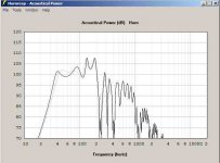 TH_115_SPL1_v_SPL2.jpg22.5 KB · Views: 262
 -
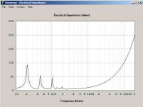 TH_115_Imp1_v_Imp2.jpg17.9 KB · Views: 258
 -
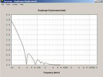 TH_115_Disp1_v_Disp2.jpg19.4 KB · Views: 258
 -
TH115_8.txt1,004 bytes · Views: 84
-
TH115_2.txt1,007 bytes · Views: 74
-
TH115_1.txt1,004 bytes · Views: 72
My conclusions are simple. It does not look like there is anywhere near to 61cm of additional path length v. a SS15-style enclosure w/ the driver at the same point in the box. It does not look like there is any chance, that the fb has changed from 37Hz to 28Hz through the modifications that have been suggested going from the TH-115 to the TH-118.
A more accurate analysis will require extensive work in AkAbak.
I'll attach my files.
Regards,
Thanks Oliver. Did you include the effect of the increased volume between the cone and S2 in the TH118? It should be somewhat easy to come up with a reasonable estimate (flat disk of diameter ~16.5" and depth 0.75" caused by the adapter plate, plus the increase in volume as a results of the larger cone of the 18" driver).
Also, to model the effect of the adapter plate on S4 to S5, try decreasing S4 and S5 by about 100cm^2 each.
Hi Brian,
I ran out of time, so I just entered the 18" parameters into the simultion w/ the increased compression, and long L34. I did go into the Wizard, and there is no rational way you can get anywhere near 28Hz (or so) by increasing S2 to reflect the additional baffle board, or by decreasing S4. In Hornresp you cannot simulate what the extension into the horn path for mounting the larger driver will do. This will have to wait for an AkAbak session.
Regards,
Last edited:
My conclusions are simple. It does not look like there is anywhere near to 61cm of additional path length v. a SS15-style enclosure w/ the driver at the same point in the box. It does not look like there is any chance, that the fb has changed from 37Hz to 28Hz through the modifications that have been suggested going from the TH-115 to the TH-118.
A more accurate analysis will require extensive work in AkAbak.
Hi Brian,
I ran out of time, so I just entered the 18" parameters into the simultion w/ the increased compression, and long L34. I did go into the Wizard, and there is no rational way you can get anywhere near 28Hz (or so) by increasing S2 to reflect the additional baffle board, or by decreasing S4. In Hornresp you cannot simulate what the extension into the horn path for mounting the larger driver will do. This will have to wait for an AkAbak session
Well, your sim shows the midpoint between the impedance peaks around 32 hz so you're on the right track but you didn't sim the effect of the driver mass loading or the stub. (I assume you didn't sim the stub, there's not enough segments in Hornresp to make a bunch of abrupt changes in csa to form that section properly.)
I'm assuming you also did not include the grill rails or the grill.
So you're at 32 hz and still need to account for a bunch of mass loading effects.
I'm not sure how you calculated path length through the cone but Brian's drawing below is off by several inches in the cone section of path length alone. Even mine drawn is green is probably too short, and it's several inches longer than Brian's.
Anyway, this is somewhere between frustrating and funny. It seems like you guys are saying this cab can't produce the measurements it does, like it defies physics or something. The plans are there, the measurements are there, if it's simulated properly the measurements and sims WILL agree with reason, as always.

I'm not sure how you calculated path length through the cone but Brian's drawing below is off by several inches in the cone section of path length alone.
If that was the case, and I'm pretty certain that it's not. then the Fb for my sim would be higher than that of the TH115, which shares the same box size and layout of the TH118. It in fact predicts an Fb that is a bit LOWER than the TH115's Fb, which can easily be explained by the slightly greater expansion between S1 and S4 in the TH115.
Anyway, this is somewhere between frustrating and funny. It seems like you guys are saying this cab can't produce the measurements it does, like it defies physics or something.
That's not what we're saying at all.
Hi Brian,
I ran out of time, so I just entered the 18" parameters into the simultion w/ the increased compression, and long L34. I did go into the Wizard, and there is no rational way you can get anywhere near 28Hz (or so) by increasing S2 to reflect the additional baffle board, or by decreasing S4. In Hornresp you cannot simulate what the extension into the horn path for mounting the larger driver will do. This will have to wait for an AkAbak session.
Regards,
I added in a Vtc of about 7.5 litres (the estimate given by HornResp in the "driver front volume" wizard). It drops the Fb in the sim from 37 Hz to 36 Hz.
The Fb looks a bit high. Was the sim supposed to use all exponential segments?
I think Danley does his measurements @28.3W, 10M.
Right, though at 10 m, it takes 100 W to = 1 W/m.
GM
Extension of Post #68 and #70
Hi Y'all,
This is an interesting subject, isn't it?
I make no claims of accuracy, and this is only an attempt to clarify for myself, what the result of putting a large 18" driver into the drawing that was presented on speakerplans.com (see: link in Post #44) would be.
A few explanations, to the Derived TH-118 drawing:
As a driver for the drawing I used an 18TBX100, that's what I had in my drawing driver library. In the simulation I used the 18TBW100.
I did not worry about the driver/cone volume as I'm working of the cross-sectional areas. Once I know the, e.g.: cone cross-sectional area @ S2 I then divide it by the common internal enclosure width to arrive @ a length that I can use in the enclosure development (roll-out?). This is just for the drawing. For Hornresp @ S2 you have the sum of the cone, and the mounting baffle (hole) cross-sections. @ S4 you have the standard free duct cross-section minus the estimated cross-sectional displacement of the driver @ S4.
As to Exp v. Par, the horn is an exponential horn, still in some places it might be better to use PAR, but overall, and especially in the long runs that combine multiple individual horn segments, I feel Exp is more accurate. Accuracy is going to be limited more by the number of segments in Hornresp in this particular case. I have taken the attached simulation, and moved the sliders around in the Wizard to find a better "simulation", looks to me like (within reason) this is pretty much it. Changing the L34 segment to Par does not change the SPL much, and changing the L23 segment to Par does not reflect the horn flare.
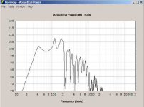
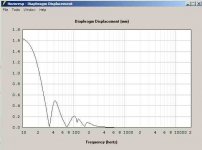
As to fb, the Diaphragm Displacement shows a minimum of about 34Hz for the Derived TH-118, so that's what I'd go with. If I eyeball some centerpoint between the two lowest impedance peaks I end up w/ 29Hz. The total horn length L15 would indicate a quarter wavelength of ~27.1Hz, so the length is there.
Regards,
Hi Y'all,
This is an interesting subject, isn't it?
I make no claims of accuracy, and this is only an attempt to clarify for myself, what the result of putting a large 18" driver into the drawing that was presented on speakerplans.com (see: link in Post #44) would be.
A few explanations, to the Derived TH-118 drawing:
As a driver for the drawing I used an 18TBX100, that's what I had in my drawing driver library. In the simulation I used the 18TBW100.
I did not worry about the driver/cone volume as I'm working of the cross-sectional areas. Once I know the, e.g.: cone cross-sectional area @ S2 I then divide it by the common internal enclosure width to arrive @ a length that I can use in the enclosure development (roll-out?). This is just for the drawing. For Hornresp @ S2 you have the sum of the cone, and the mounting baffle (hole) cross-sections. @ S4 you have the standard free duct cross-section minus the estimated cross-sectional displacement of the driver @ S4.
As to Exp v. Par, the horn is an exponential horn, still in some places it might be better to use PAR, but overall, and especially in the long runs that combine multiple individual horn segments, I feel Exp is more accurate. Accuracy is going to be limited more by the number of segments in Hornresp in this particular case. I have taken the attached simulation, and moved the sliders around in the Wizard to find a better "simulation", looks to me like (within reason) this is pretty much it. Changing the L34 segment to Par does not change the SPL much, and changing the L23 segment to Par does not reflect the horn flare.
As to fb, the Diaphragm Displacement shows a minimum of about 34Hz for the Derived TH-118, so that's what I'd go with. If I eyeball some centerpoint between the two lowest impedance peaks I end up w/ 29Hz. The total horn length L15 would indicate a quarter wavelength of ~27.1Hz, so the length is there.
Regards,
Attachments

Right, though at 10 m, it takes 100 W to = 1 W/m.
GM
Yup, I meant 28.3V, not 28.3W.. 🙂
B.
If that was the case, and I'm pretty certain that it's not. then the Fb for my sim would be higher than that of the TH115, which shares the same box size and layout of the TH118. It in fact predicts an Fb that is a bit LOWER than the TH115's Fb, which can easily be explained by the slightly greater expansion between S1 and S4 in the TH115.
Your path length red line in the drawing above shows a triangle (one bend) going through the cone area, and it only dips a couple of inches below the baffle board. My green path line is a lot more accurate and probably still too small. The cone is huge, so big they had to put fit a larger baffle to mount it to, the path through the cone is a lot longer than you have shown, and even my green line is probably way too conservative. But again, I'm just repeating myself. If you drew in a double baffle board and a driver to scale and drew in the actual path you would see your estimate is way too short through that section.
That's not what we're saying at all.
Honestly I have no clue what you are saying then. You discount the path length the stub, the mass loading of the driver and the extra baffle board, haven't acknowledged the grill rail and grill even exist - but you can't figure out why the cab measures the way it does and actively seek answers like V shapes in the throat that clearly are not in the plans, and if I understand correctly you are simulating volumes in the throat which are also not in the plans. I'm at a loss. Why not just sim the plans as they are? You'll find the sims match the measurements like they always do. Otherwise the plans are wrong or the measurements are wrong. It's as simple as that.
Last edited:
Post #75 - Derived TH-118 Simulation
Hi Y'all,
Forgot to post the simulation(s) for the Derived TH-118.
Here are two simulation, one using TH, and the other using TH1 (as shown there is a reduction of the mouth area reflecting a 1"(2.54cm) wide frame. Just play around w/ the Wizard, e.g.: w/ mouth size reductions.
I do not believe, that Hornresp simulations suit a case like this, it would be better simulated using lots of individual segments in AkAbak. Just to get around the general driver area (in the drawing from S1 to 1) takes about 5 to 7 segments (?). Still, the final result will probably not reflect the changes induced by measuring @ 10m/28.3V, nor will these types of simulations correctly predict the exact behaviour @ maximum power and excursion. I don't think that's what these programs were designed to do.
In the end I side with Tom Danley: "Measurements trump simulations."
Regards,
Attachments
I do not believe, that Hornresp simulations suit a case like this, it would be better simulated using lots of individual segments in AkAbak.
Absolutely agree, it's pointless to sim this with Hornresp, there's way too much going on in this cab, Hornresp doesn't have nearly enough segments to even come close.
In the end I side with Tom Danley: "Measurements trump simulations."
Regards,
At the end of the day the sims always end up pretty close. Until you start getting up into pretty serious power compression and other types of nonlinearities the sims are pretty valid. None of DSL's stuff is anywhere near stressed at the power levels they are measured at. I think the 10 meter measuring distance introduces a lot more variation than the power level, but even that can be simulated. Also the "barn door" effect on the bigger cabs can introduce some variation from a simple sim (and that can be simulated too), but this cab isn't that big, in this case the sims should match the measurements reasonably well, but it would take a concerted effort, redrawing the cab as a straight flare, making sure the flare rate changes were well documented and doing a sim with at least a dozen segments. A simple Hornresp sim with estimated flare dimensions and a single flare rate (or even a couple of different flare rates) isn't even going to get in the right ballpark.
Your path length red line in the drawing above shows a triangle (one bend) going through the cone area, and it only dips a couple of inches below the baffle board. My green path line is a lot more accurate and probably still too small. The cone is huge, so big they had to put fit a larger baffle to mount it to, the path through the cone is a lot longer than you have shown, and even my green line is probably way too conservative. But again, I'm just repeating myself. If you drew in a double baffle board and a driver to scale and drew in the actual path you would see your estimate is way too short through that section.
The increased volume at S2 caused by the baffle and the larger cone can be simmed by including a throat chamber of equivalent volume there in the sim. There's no need to make any adjustments to the path length at S2 in the sim because of the inclusion of an adapter board and a larger driver when changing a TH115 to a TH118. HornResp even includes a wizard to estimate the volume in front of the driver's cone so you can include it in the sim like I've suggested.
As for my path length estimate "dipping only a couple of inches below the baffle board", that's pretty much where it should be when one takes the position of the driver's cone into consideration, then divides the distance between the cone and the horn's internal panel in half at that point to determine where the estimate for the path length should reside. However, even if it is off by a few inches (and I don't think it is), that's still not enough to make any significant change to Fb.
- Status
- Not open for further replies.
- Home
- Loudspeakers
- Subwoofers
- Dual 18 Tapped Horn Design Concept