If I'm understanding you right, we can now buy any remote-controlled-motor-pot kit or module from anywhere, desolder the motor pot which is part of that module, extend the two wires which went to the old motor pot's motor so that they now stretch to your Bourns pot's motor leads, and then we're good to go. The electrical drive currents, speeds, etc, which drive one motor pot should be pretty much the same for another, right?
Nope, you cannot make that assumption. The control circuit must be appropriate to the motorized pot being used. The Bourns pot that I chose runs at 4.5 volts DC and draws 100ma. The adjusted main PCB is but the first step. I am making it available to those savvy builders that want to design their own MCU controller.
Carl, what knobs are those? Look like Levinson..Hmm ...
My wife gave me grief for posting those PICs with the 'crazy knobs'. So here are a few more but with the knobs tightened down.


Yea she's right, they do look better.
Hey Carl, is there a published schematic for the amp as well? Thx much!
This project is a preamplifier only. It based upon an article published by Douglas Self in Linear Audio magazine. You will need to pair it with your favorite audio amplifier.

Carl, yes, I mean of course the preamp. Is the schematic available somewhere online? Thanks again
Those knobs are made by Kilo International. They are KILO #HD-75-3-7 knobs
http://www.kilointernational.com/
http://www.kilointernational.com/
I ship the schematic with the PCB kit. The preamplifier is based upon an article by Douglas Self in the #5 Linear Audio magazine. The article can be bought online.Carl, yes, I mean of course the preamp. Is the schematic available somewhere online? Thanks again
A very nice publisher made it freely available there:I ship the schematic with the PCB kit. The preamplifier is based upon an article by Douglas Self in the #5 Linear Audio magazine. The article can be bought online.
https://linearaudio.net/douglas-self-preamp-linear-audio-vol-5
Ah, good! Altho Jan and I had talked about putting the documents zip online some time ago, I had not realized that he had done it.
The circuit schematic in the package is current. However the power supply is not what I supply in the kit these days.
The circuit schematic in the package is current. However the power supply is not what I supply in the kit these days.
Goldpoint now offers a 47-step attenuator. I have developed an Arduino based board to control the Bent Audio stepper motor. A small quantity of these motors are still available. As the Arduino offers the possibility of much more functionality than just volume control, I added outputs to control relays and an I2C port for an OLED display. If there is interest, I will start a new thread.
Attachments
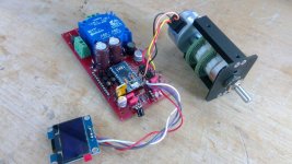
Yes, excited to see details in a new thread. Nice work!Goldpoint now offers a 47-step attenuator. I have developed an Arduino based board to control the Bent Audio stepper motor. A small quantity of these motors are still available. As the Arduino offers the possibility of much more functionality than just volume control, I added outputs to control relays and an I2C port for an OLED display. If there is interest, I will start a new thread.
I fail to understand what you're trying to tell us (which, of course, may be my fault):Goldpoint now offers a 47-step attenuator. I have developed an Arduino based board to control the Bent Audio stepper motor. A small quantity of these motors are still available. As the Arduino offers the possibility of much more functionality than just volume control, I added outputs to control relays and an I2C port for an OLED display. If there is interest, I will start a new thread.
The preamp was designed for 5k linear pots, while the attenuator which you mention starts at 10k log. How should I integrate it into the preamp?
Fair question. Earlier in this topic a number of volume controls were discussed, all with the intent of being remote controlled, but some controls also were suggested that could be seen as offering better performance of the volume control stage. If I understand Mr. Self correctly, the active volume control circuit in this preamp has the primary benefit of offering a closer approximation of "logarithmic" attenuation than traditional "logarithmic" taper pots. However, it may still suffer from channel-to-channel inaccuracy, which is a function of the mechanical alignment of the two wafers. Stepped attenuator solutions, either rotary switch based or relay based, can offer more ideal performance in this aspect of their behavior.
Relay based attenuators have several disadvantages as well, one of them being that they offer no visual clue as to what attenuation they are set for. This can be dealt with by displaying their setting on a display. But there still remains the issue of the initial setting of the attenuator when the circuit is first powered up. A solution to both issues is to use a pot with a DC voltage across it, read the DC voltage with an ADC, and then translate the reading into a setting for the attenuation relays. All well and good, but certainly a rather complex solution.
A rotary switch based stepped attenuator, has a somewhat more complex issue with motorization, as it must be driven with a stepper motor, rather than a simpler DC motor that can be used to drive a linear pot. The solution I offered is simply that: a way of adding the remote control function to a stepped attenuator rotary volume control. In terms of how it would be applied to the pre amp in this thread, it would replace the entire active volume control stage. The same would be true of a relay based stepped attenuator. The stepped attenuators, by the value of the resistors chosen for each step, create the logarithmic function. There is no point to placing a precision stepped attenuator inside a feedback loop.
Please understand that I am in no way suggesting that the motorized linear pot, placed inside the feedback loop to become an active volume control, is not an excellent solution. It was only that the discussions in this thread sent me down a different path and I wanted to share that work if any others are interested.
Another solution for digitally controllable volume would be the PGA2310:
https://www.ti.com/lit/ds/symlink/pga2310.pdf
Quite good specs for an IC solution, available as through hole and smd device, but quite expensive.
In case you want to control it with an Arduino, there is a library available:
https://github.com/kashev/ti-pga2310
I'd use it with an IR receiver and a rotary encoder.
Just another hint 😉
To use any of these volume control solutions you will need to bypass (replace??) everything between C40 and C47 on the main board.
If the original volume control shall be kept but digitally controlled, then I still think using the MCP41HVX1 or MCP45HVX1 is the simplest solution.
You are right! That MCP41HV51-104E/ST part looks very interesting.
- Home
- Source & Line
- Analog Line Level
- Doug Self Preamp from Linear Audio #5