Hi Forr,
Should I change something please for a 100 K inputt amp and a DAC outputting 1.5 V ?
Should I change something please for a 100 K inputt amp and a DAC outputting 1.5 V ?
Last edited:
Currently the input impedance is 50 kOhm on the pin2 and the pin3 of the XLR socket. Is that not enough for your DAC output wihch should have a low output, probably far less than 470 Ohm ? If the gain of the preamp is too high, do just as JMK did or insert an attenuator before the input of the power amp. Built 680 and 330 Ohm resistors, the signal will be lowered by 9.7 dBHi Forr,
Should I change something please for a 100 K inputt amp and a DAC outputting 1.5 V ?
Impressive build. Would you be able to show us inside as well?
As requested.
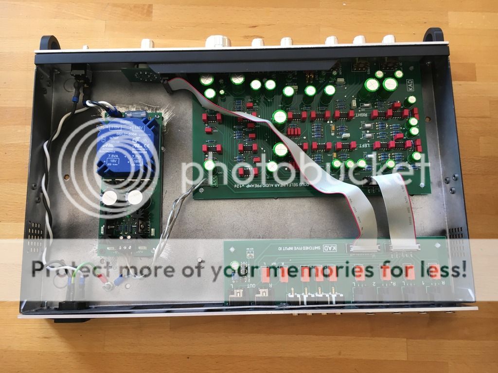
I hate drilling holes for standoffs, so I've used nylon computer standoffs to elevate the boards (main amp and I/O PCBs) off the floor of the enclosure. But the boards are really held in place by the nuts on the front panel and the screws on the back panel. Only the power supply PCB is mounted by standoffs that are affixed to the bottom of the enclosure. And even here, I used ColdWeld adhesive rather than drill holes.
** Doug Self Preamplifier PCB Kits **
Here is the revised list of interested parties for this last round of Doug Self preamplifier PCB kits.
pchw - 1 kit - PAID
kissmurphy - 2 kits - PAID
Rick G - 1 kit - PAID
Flugelmere - 2 kits - PAID
hasenmuehle - 1 5x1 IO kit - PAID
gorkyh - 1 kit - PAID
J.M.K - 1 kit - PAID
quicklizard - 1 kit - PAID
graemed - 1 kit - PAID
Eldam - 1 kit - PAID
canyoncruz - 1 kit - PAID
sek - 1 kit - PAID
Mraudionut - 2 kits - PAID
Art M - 1 kit - PAID
Lutto - 2 kits - PAID
*> KITS WERE SHIPPED TO THE ABOVE PARTIES SATURDAY 10-01-2016 <*
PICs of the Latest Doug Self Preamplifer
Below are PICs of the rev 1.3 PCB. Performance is identical to previous version. Changes for v1.3 amount to ...
#1) The BOM was made simpler. Previous version called for 2 version of 470uF capacitors. The board now accepts 6 Nichicon UES1V471MHM capacitors
#2) Some builders complained that the power connector needed to larger to accept a larger gauge of wire. As result the EURO power connector is now 5mm on center. It is specified to be a Phoenix #1755910 connector or equivalent
Last edited:
As requested.
I hate drilling holes for standoffs, so I've used nylon computer standoffs to elevate the boards (main amp and I/O PCBs) off the floor of the enclosure. But the boards are really held in place by the nuts on the front panel and the screws on the back panel. Only the power supply PCB is mounted by standoffs that are affixed to the bottom of the enclosure. And even here, I used ColdWeld adhesive rather than drill holes.
You inspired me. I just ordered a case from the DIYaudio store.
As requested.
I hate drilling holes for standoffs, so I've used nylon computer standoffs to elevate the boards (main amp and I/O PCBs) off the floor of the enclosure. But the boards are really held in place by the nuts on the front panel and the screws on the back panel. Only the power supply PCB is mounted by standoffs that are affixed to the bottom of the enclosure. And even here, I used ColdWeld adhesive rather than drill holes.
Wow. Neat as...
Hope my build turns out to look as professional as this one. The enclosures readily available in Aus are not as good as this.
Thank you HaroldHill.
Graeme
Hi Carl,
Thanks for posting the nice pics. 🙂
Excellent!
Thanks for the improvements and for making it a little easier.
It doesn't look like you ran into any show stopper issues with the test build.
Cheers!
Rob
Thanks for posting the nice pics. 🙂
Below are PICs of the rev 1.3 PCB. Performance is identical to previous version.
Excellent!
Changes for v1.3 amount to ...
#1) The BOM was made simpler. Previous version called for 2 version of 470uF capacitors. The board now accepts 6 Nichicon UES1V471MHM capacitors
#2) Some builders complained that the power connector needed to larger to accept a larger gauge of wire. As result the EURO power connector is now 5mm on center. It is specified to be a Phoenix #1755910 connector or equivalent
Thanks for the improvements and for making it a little easier.
It doesn't look like you ran into any show stopper issues with the test build.
Cheers!
Rob
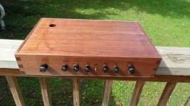
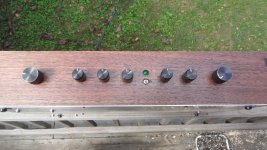

Love the wood case, is that mahogany ? also how did you get the printing on the front panel.
PJN
PJN
Hi Carl,
Thanks for posting the nice pics. 🙂 Excellent!
Thanks for the improvements and for making it a little easier.
It doesn't look like you ran into any show stopper issues with the test build.
Cheers!
Rob
Yes!
With the exception of one cold solder joint (working too late into the night ...) the new boards came right up.
I have been listening to it intently for the last week. All is well.
Thanks again to Douglas Self and Jan Didden for making this available to the DIY community.
"Love the wood case, is that mahogany ? also how did you get the printing on the front panel."
PJN,
i believe it is Walnut. My Brother gave it to me a while back. As for the Printing, go to
Waterslide Decal Paper, Image, Transfer Paper, Iron On, Decals. Black on the dark wood is kinda hard to read from a distance but looks COOL to me. Had to get the wife (a typesetter by trade) to re-do the template for the correct size of the front panel so everything aligned up properly.
Rick
You inspired me. I just ordered a case from the DIYaudio store.
Wow. I actually inspired someone to do good! (I hope it turns out well!)
Hi Carl,
Thou shalt not solder after midnight! 😉
Cheers!
Rob
With the exception of one cold solder joint (working too late into the night ...) the new boards came right up.
Thou shalt not solder after midnight! 😉
Cheers!
Rob
Boards arrived today. Thanks Carl.
Also, is there a new BOM somewhere for this version.?
Rick
I emailed it to you. I'll send you a private message with the files.
Here is my Preamp Case. Hard to do it justice with my camera & skill level. 🙂
Lovely job. Looks so special in timber. Congratulations.
Graeme
Using less voltage ?
Hi !
I already have a very good +/-15 Volts linear PSU.
Is there any drawback in using +/-15V,
instead of the +/-17 Volts recommended in the documentation ?
Thanks a lot ......
JM
(17V is the maximum voltage acceptable according to LM4562's datasheet)
Hi !
I already have a very good +/-15 Volts linear PSU.
Is there any drawback in using +/-15V,
instead of the +/-17 Volts recommended in the documentation ?
Thanks a lot ......
JM
(17V is the maximum voltage acceptable according to LM4562's datasheet)
Last edited:
- Home
- Source & Line
- Analog Line Level
- Doug Self Preamp from Linear Audio #5