Nope. This preamplifier incorporates what is called an active volume control. The AMB volum control cannot be used without major changes to the preamplifier design.Would it be possible to integrate the AMB LCDuino as a remote volume control and display such as in the alpha10 preamp?
It could be used with or without a physical pot. https://www.amb.org/audio/alpha10/
The signal does not pass through the ALPS pot, it's relative position is used to determine the volume.
Just to make sure I'm not entirely missing the point here, the LCDUino is Arduino based and sends instructions to a module via i2c.
Since you had mentioned BBB somewhere in this thread, I thought the firmware for this could be modified somehow to support this preamp
Just to make sure I'm not entirely missing the point here, the LCDUino is Arduino based and sends instructions to a module via i2c.
Since you had mentioned BBB somewhere in this thread, I thought the firmware for this could be modified somehow to support this preamp
The 5K linear pot that is described in this project is key to making the circuit work. The AMB attenuator network in the AMB project is not equivalent. If this preamplifier was a traditional pot shunting to ground it would work, but of course that is not the case.
This thread describes how an active volume control works: https://www.diyaudio.com/community/...-with-balanced-output-using-2-op-amps.270052/
This thread describes how an active volume control works: https://www.diyaudio.com/community/...-with-balanced-output-using-2-op-amps.270052/
A simple linear 5k digipot might be possible, but you'd need to ensure it couldn't be over-voltaged, and drive it from an Arduino or similar.
The Self preamp is +/-15V out of the box I believe, digipots don't go that high to my knowledge, +/-5V is more likely to be findable.
And of course you could use figure out a stepped attenuator that's equivalent to a linear pot, though that's rather unwieldy.
The Self preamp is +/-15V out of the box I believe, digipots don't go that high to my knowledge, +/-5V is more likely to be findable.
And of course you could use figure out a stepped attenuator that's equivalent to a linear pot, though that's rather unwieldy.
I think the best approach would be to replace the entire active volume control stage with the stepped attenuator circuit. Easy enough to do as the active volume stage has locations for input and output coupling capacitors, so the stage is easy to isolate. I find the idea a fascinating option for those who want an IR remote volume circuit.
…or use a motorized pot. Looks like there are kits including displays for that as well, but they might need some tweaking (I havne‘t checked) before they can be used as a drop-in replacement for a manual pot.
I don't understand why some here want to break everything. The Self baxandal volume control is excellent and very low-noise. Why should you replace this with rattle relays? Doesn't make sense to me.
The MCP41HV51-502E/ST is a 5K digipot that will do +/-18V (5V for digital control signals). I see Mouser have them in stockA simple linear 5k digipot might be possible, but you'd need to ensure it couldn't be over-voltaged, and drive it from an Arduino or similar.
The Self preamp is +/-15V out of the box I believe, digipots don't go that high to my knowledge, +/-5V is more likely to be findable.
You ruin the excellent measurements with a digital pot.The MCP41HV51-502E/ST is a 5K digipot that will do +/-18V (5V for digital control signals). I see Mouser have them in stock
Not so! There is no digital signal present within the analogue side unless due to poor circuit layout.You ruin the excellent measurements with a digital pot.
There are many reasons, from just wanting a remote-control volume function for convenience, to really needing one because of physical limitations.
Not too long ago I set out to add a remote controlled volume control to this preamplifier. My plan was to use a motorized 5K pot made by Bourns #PRM162-K415K-502B1, stocked by Mouser. My plan included a blue character display all under the control of an Arduino Nano controller. The digital components were to be on a separate PCB so as to keep it away from anything analog. But as happens all too often, I saw something shiny and got distracted. I have yet to finish the project.
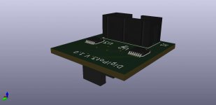
A while back, I put together a piggy-back board to directly replace the manual volume pot on my Self 2012 pre-amp which also implements the Baxandall volume control . It uses two MCP45HV51-502E/ST devices (I2C version of the digital potentiometer), one for each channel and was controlled by a home-brew ATMega16 microcontroller board (similar to an Arduino but running native C code). An Arduino or anything similar would do the controller job quite happily.
I never got to implement this on my existing preamp as other projects came along instead but if it's of any use to anyone, here it is.
I never got to implement this on my existing preamp as other projects came along instead but if it's of any use to anyone, here it is.
Attachments
Last edited:
Yes, I too am interested in the generic question: how does one integrate a motor-pot with this preamp, for volume control?Would it be possible to integrate the AMB LCDuino as a remote volume control and display such as in the alpha10 preamp?
It could be used with or without a physical pot. https://www.amb.org/audio/alpha10/
My plan was to use a simple Arduino Nano processor. An infra-red receiver reads from a standard hand-held remote control and spins the motor thru a simple bridge circuit. I had planned to build the whole thing on the back of a PCB that has a display showing volume level relative to zero. Overall pretty simple.Yes, I too am interested in the generic question: how does one integrate a motor-pot with this preamp, for volume control?
If you used the 5K linear motorized pot Carl previously identified, you then need some way to drive it. A simple micro to decode the IR signals and a driver chip. The attached schematic shows such a circuit. Then all you need is the firmware. The code I used as a starting point was from

Sorry, that post sent before it was complete. The code for the micro is from picprojects.org.UK in its archive page as "3-Channel IR Relay Controller". It's in assembly language for those who really want to go "old school".
I received the boards this week, thanks Carl!
I'm acquiring parts and planning for the build, 2 questions:
1) The selector switch, Lorlin CK1059 has a very long shaft, different than the one pictured here. Is that the correct P/N?
2) What is the correct grounding scheme? Aside from safety earth, I thought we need to only take the PSU 0V to chassis, but the I/O board also has a pad for GND and XLR Pin 1, so was curious if any of those need to be connected as well
- Home
- Source & Line
- Analog Line Level
- Doug Self Preamp from Linear Audio #5