I ran out of 15000uf caps and have 4 3300uf caps. How can I use these on the new board and how many .47 ohm caps do I need to use?
I actually am working through PCB boards I acquired and some I just purchased.
-F4
-F5
-M2x
I could swap any boards to make them work.
-F4
-F5
-M2x
I could swap any boards to make them work.
I was thinking 2 33000uf caps on the inside sockets would work but need to know how many .47 ohm resistors to use.
Input snubber
Sorry, newbie question coming:😱
I am thinking about using the Toroidy Audio Grade 400VA 2 x 18V. Does someone know the values for the input snubber (or can me help to interpret what I have found)?
500VA is said to be Cx: 10nF, Cs: 150nF, Rs: 7Ω / 7Ω. (On this list.) I can't use that for the 400VA, correct?
Someone measured it in this discussion, but I'm struggling to understand which value to use practically.
Sorry, newbie question coming:😱
1)
2) The input snubber is something worth doing. (Ignore the output snubber. ) Because you are using the AS-4218, I know that the values of 0.01uF+12ohm and 0.15uF work well.
I am thinking about using the Toroidy Audio Grade 400VA 2 x 18V. Does someone know the values for the input snubber (or can me help to interpret what I have found)?
500VA is said to be Cx: 10nF, Cs: 150nF, Rs: 7Ω / 7Ω. (On this list.) I can't use that for the 400VA, correct?
Someone measured it in this discussion, but I'm struggling to understand which value to use practically.
On the First Watt PS drawing, could the capacitor in parallel to the 240VAC line, be something like that ?
ECQ-U2A332KL Panasonic | Mouser
ECQ-U2A332KL Panasonic | Mouser
Last edited:
For a class AB amp, do you think dual mono is better than 2x capacitance shared? Or does it depend on the magnitude of the capacitance being doubled?
For example, on a 150W @ 8 Ohms amplifier, would you rather have 20mF per rail per channel or 40mF per rail shared by both channels?
For example, on a 150W @ 8 Ohms amplifier, would you rather have 20mF per rail per channel or 40mF per rail shared by both channels?
6L6Just saw this.
No. Don't do that. One thermistor in series with the AC primary only.
The other CL-60 goes on the output of GND at the power supply.


The wires that run to and from the PS board appear to be a fairly large gauge, what gauge is best for that application?
Now for the fuse fitting the IEC appliance inlet C14 of the A4 Deluxe chassis back plate.
As I will use 240VAC it should be 1.25A slow blow.
Is the size 5x20mm ?
As I will use 240VAC it should be 1.25A slow blow.
Is the size 5x20mm ?
May be some of you has a good and simple way to separate the diode board.
Any suggestion welcome.
Any suggestion welcome.
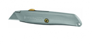
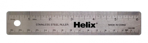
1. Utility Knife
2. Steel Ruler
3. Patience
_
That is exactly what I did !
Here is where I am at the moment :
F-PSU-in-process.jpg - Google Drive
F-PSU-finished.jpg - Google Drive
F-PSU-in-process.jpg - Google Drive
F-PSU-finished.jpg - Google Drive
I'm not normally much of a video watcher, but that Indian amplifier PSU build was great. I get far too precious with stuff whereas he just gets on with it.
BTW, aren't the DIYA Store boards scored? Can't you just snap off the diode section?
BTW, aren't the DIYA Store boards scored? Can't you just snap off the diode section?
Exactly! I ordered power supply boards twice over the past year-and-a-half and both times they were snapped apart, courtesy of the US Postal Service. I hope the diyAudio store has found a better way of packaging other than in lightly padded envelopes which are easily folded to stuff into a mailbox.
Here is where I am at the moment :
F-PSU-in-process.jpg - Google Drive
F-PSU-finished.jpg - Google Drive
Anyone can tell me if I missed anything here (beside the led ) ?
- Home
- Amplifiers
- Power Supplies
- diyAudio Power Supply Circuit Board v3 illustrated build guide