Marks investigation of thermistors is a very thoroughly conducted experiment. As a bench scientist (though not in engineering), i think the effort and care taken in the design and execution of his experiment, and the detail with which it is documented is commendable. I also think his conclusions speak for themselves. His proposed alternative to the CL-60 is will provide you better inrush current limiting (ie lower peak current on startup), while dropping slightly more voltage and idling hotter. It is also cheaper. To my mind this is the most solidly founded advice you can chose to go from.
I read the thread again.
As suggested I will be using SL15-60002, and not the CL60. Many users on the m2x report fuses getting blown over time, dont like the prospect of changing fuses, so the SL15-60002 it will be. Thanks for the advice.
As suggested I will be using SL15-60002, and not the CL60. Many users on the m2x report fuses getting blown over time, dont like the prospect of changing fuses, so the SL15-60002 it will be. Thanks for the advice.
Hi,
I have some questions about the rectifier diodes:the FEP30DP is twice the cost of the MBR20200CT, I prefer to buy the cheapest, are there performance differences between these types?
MBR20200CT-BP 0,88 €
MBR20200CT-BP Micro Commercial Components (MCC) | Mouser Belgique
MBR20200CTG 1,10 €
MBR20200CTG ON Semiconductor | Mouser Belgique
FEP30DP-E3/45 2,10 €
FEP30DP-E3/45 Vishay Semiconductors | Mouser Belgique
Another question:
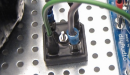
1)See screenshot, I regularly see this connector terminal block being used (looks useful and tidy), does anyone know what this is called or know a parts number?
2)Anyone have a suggestion for diode heatsink electrical isolation pad type?
1)See screenshot, I regularly see this connector terminal block being used (looks useful and tidy), does anyone know what this is called or know a parts number?
2)Anyone have a suggestion for diode heatsink electrical isolation pad type?
Attachments
Last edited:
It's a monolithic bridge rectifier. See post #1 of this thread, then do a search for more info and suggested part numbers. Several members, including me, have posted recommended part numbers for use with Pass class A amps.
Thanks for the info. Sorry, I was confused because it was not listed in the BOM.
Using 2 monolithic bridges is a lot cheaper then the diode bridge, and more simple.
I found this bridge, seems like a good option, what do you think?
Vishay GBPC3510-E4/51 BRIDGE RECT 1PHASE 1KV 35A GBPC
GBPC3510-E4/51 Vishay Semiconductor Diodes Division | Discrete Semiconductor Products | DigiKey
I suppose I also need isolation pads for mounting the bridge on the bottom plate?
Is there anything special I need to know if I use a monolithic rectifier instead of the diode board?
The one you link should work just fine. I think the official recommendation is 35A/600V minimum so that is plenty. The package is insulated so no need for pads, it mounts directly to the chassis baseplate.
Hi all
Planning to built a F5, I would go with the bridges rectifiers . From the guides I can see that for the DIY PSU board, C17 & C18, R11 & R12 aren't populated !
What are they for, can we go without it ?
Planning to built a F5, I would go with the bridges rectifiers . From the guides I can see that for the DIY PSU board, C17 & C18, R11 & R12 aren't populated !
What are they for, can we go without it ?
Hi,
I have difficulty for the wiring of the following Toroidy transformer using the First Watt shematic PSU.
TTSA0400 - Transformer AUDIO TSA400VA - voltage to 50V - Shop Toroidy.pl
It seems this transformer has only two primaries wires blue/blue and four secondaries wires.
For 240v main power supply as used here in Europe :
1) So you place the Ceramic Disc Capacitor in parallel between the two blue wires but you can't place a Thermistor as requested so there is none ! Am I correct on that ?
2) The second Thermistor , which is a CL60 should be on the DC circuit from the output of one rectifier to ground ?
Thanks
If it has only one set of primary wires (which is quite normal) you just connect the CL60 (NTC resistor) as a serial connection (e.g. between the 230 VAC "Phase" and one of the primary wires of toroid and the other primary wire goes to "Neutral"). I assume the other CL60 is used to raise signal Gnd from chassis (earth)? ….the signal Gnd is on the DC/output side of the PSU board (assuming you don't any additional filtering).
Don't connect the CL60 in parallel.........
Don't connect the CL60 in parallel.........
Meper,
Would it be something like that ?
Any idea of the value of C9 for the 240v main ?
240 PSU.jpg - Google Drive
Would it be something like that ?
Any idea of the value of C9 for the 240v main ?
240 PSU.jpg - Google Drive
2) The second Thermistor , which is a CL60 should be on the DC circuit from the output of one rectifier to ground ?
Just saw this.
No. Don't do that. One thermistor in series with the AC primary only.
The other CL-60 goes on the output of GND at the power supply.


Last edited:
I didn't look carefully at the shematic I guess.
So the CL60 is ground main supply (on the 240v side of the transformer) to PSU ground or chassis, correct ?
So the CL60 is ground main supply (on the 240v side of the transformer) to PSU ground or chassis, correct ?
One CL60 on 240vac live lead to transformer primary.
One CL60 from DC ground (PSU output) to chassis.
One CL60 from DC ground (PSU output) to chassis.
On 240 VAC side the CL60 is an inrush current limiter so here is no connection to chassis. Another use for the CL60 is as a "ground loop breaker" from Gnd (signal Gnd) of DC supply to chassis. It is important not the get confused by the different uses of these NTC's…..to avoid getting 240 AC on chassis.....
Thank you very much for these explanations, great help really.
I had to search what a NTC resistor meant and understand its functionnality, now I get why it's also called a Thermistor.
I don't know if you really realise how much helpful you have been on this, this PSU was an horror to me, I spent a good month on it trying to grab its purpose & functionnalities.
Not to mention that I could never calculate any value or choose any particular specific specification, ceramic or else.
Thanks, thanks, thanks....
It is always much more fun to find out how it works instead of just trying to put something together "blind" from a schematic (it also reduces errors). A NTC resistors is the most precise term as a Thermistor also can be a PCT (a resistor with positive temp. coefficient). You don't want one of these as inrush limiter for the power transformator.....
- Home
- Amplifiers
- Power Supplies
- diyAudio Power Supply Circuit Board v3 illustrated build guide