@meper - Thank you! I've been following your build. The photos you post and questions you ask are a huge help. Your answers to my questions are greatly appreciated along with the extra insight.
I'll take a look at some of the higher capacitance lower voltage, but the highest that I could find in Mouser was the 15k 50V. They were not in stock. Does "audio rated" mean anything in this application in a PSU? I'll give it one more look. They're not cheap, so I'd like to be thoughtful with this selection.
I added the "monolithic" rectifiers to my personal BOM along with the parts for the separate diodes + heatsinks. I greatly appreciate you explaining the potential advantages of the individual parts. I'll make the decision on what to put into the build when I start laying everything out. Now I lean toward the individual components.
I added enough parts to include the extra pi resistors if I can figure out why or why not.
I really need to organize my notes. I have been on a cut and paste frenzy. I KNOW I read somewhere (I think it was Mark) that there was a table being compiled to help newbs like me choose the right resistor and cap values. I also know it's hotly debated. This is an area way outside my pay grade. If the experts haven't reached a solid conclusion, then I don't know what to do. Essentially, one point is that some transformers / circuit combinations have enough damping to where you don't need a snubber (I think) other transformers may not. So, a snubber may be advantageous. Then it comes down to what type of snubber and how many parts and the cost. In my particular shoes, I appreciate that there are thoughtful designers/engineers that would never add extra cost or complexity to a circuit. "Don't fix what isn't broken". I also appreciate that if in certain applications the snubber could be beneficial and never hurt. To me less than a few USD in parts and my labor to install them is worthwhile IF I can get the right values.
So... I'll look for the table. I want to get all my BOMs ordered at once. Shipping is crazy, so I usually over order if there is a question of whether I need something.
Does anyone know where I could find the proper values for an Antek AS-4218 with this PSU and build? I'd be willing to buy a few values low, center, high and hone the decision with measurements later. I'd just need to know where to start.
@MrDave45 -
Thank you also! I will digest some of the math. Cut and pasted into my learning guide.
Noted re: diodes, snubbers, and capacitors. Clear as a bell.
I found huge value in reading the "why" re: the resistors - particularly the LED dropping resistors. I opened the specs for the LEDs and found that the forward voltage is 2V. No spec for "Voltage Drop". I then looked up to see if forward voltage is the same as voltage drop. The bald engineer helped me out there. It seems for this purpose I use 2V in your equation. For the LED to remain "open" I need a drop of 2V typical or 3V max or greater. With this LED it seems anything over 6V would be "bad". It seems this is at 20mA. If someone would kindly take a look at the specs to see if I have it correct for the TLHR-6400 in the BOM, I'd be grateful.
https://www.mouser.com/datasheet/2/427/tlhg640-266657.pdf
If I got it correct and copied the correct intention of your helpful exercise - 24V - 2V => 22V across the LED resistor.
22/0.02 = 1100 = 1.1k
0.02*0.02*1.1k = 0.44 further supporting using a 1/2 W resistor.
As you can see, this type of thing takes me a while to absorb nevertheless apply.
Summary - 10kohm 1/2W would be a suitable choice.
Thank you!
Last edited:
It can be difficult to get these caps. I used these:
380LX333M035A052 | Cornell-Dubilier Elektrolytkondensator, 33000μF, 35V dc, Hulmontering, levetid: 1000 (Shelf) h, 3000 (Endurance) h, | RS Components
….but they are now out of stock until september. Don't look too much at shelf live and life when in use. It is assumed that temperature are at highest rating (e.g. 85 C). Life will be at least 10 years and probably 20 at normal temperatures. I use the largest stereo Deluxe chassis as mono blocks so there is a lot of air inside them and PSU board can be placed away from the heat.
Do you need the LED? …..it will be inside the box and it is quite obvious if PSU is not working (and a LED with light in does not guarantee a working PSU). I did not install the LED. I try to omit anything that does not add any value.
@MEPER -
Thank you for the recommendation and the context! At first, I'll be using the 5U Deluxe and potentially move it to a separate enclosure later. At some point, "the numbers" just blur together. I've added your recommended cap to my BOM, and will go with it. It's a little expensive to change caps, but if I have a good engineering reason to change them later that I can comprehend, I will.
Short version re: the LED. I don't know. I am a complete newbie. I try to pick things up, but I truly don't understand the function or necessity of every part in the circuit. I've reviewed the schematic, but I can't say with any certainty whether certain parts are "needed" unless shown as optional in the BOM. Generally 6L6 and Mark explain optional parts and the tradeoffs. I missed that the LEDs were optional.
My general order of operations is:
1) Is it in the schematic?
2) Is it in the BOM? If the two don't match, then I go with the BOM. Somebody smarter than me was bold enough to add to or change something from Papa's design for a reason. Generally, those reasons seem to be making the builds more flexible for a higher variety of parts choices / variations from center point and increasing the chances for a successful build. I trust them.
3) Read as many threads as I can until my brain melts to try and understand it all.
4) When in doubt, ask the group or just do what @6L6 did. Although, I'm using 2 red instead of one red and one green LED 🙂
The short version is that I never considered it with all the other things I was trying to figure out. Good news is that I'll have the parts if I decide to put them in. The other things that may sound silly, is that when I remove a part, I struggle to know whether I need to jumper across the pads or can just leave it out. I try to figure out if it's running in parallel or series ... and then just tell myself to follow the build guide when I'm unsure. It's my first "real" amp, so I err toward whatever takes the least brainpower that stands a good chance of operating as intended. i.e.... sounding wonderful. I am not looking to build the ultimate tweaked one. If I overthink it, I'll surely goof it up.
Once again, thank you for the insight. I wish I had known enough to know whether it was "needed". Clearly not, but I didn't know that. The great news is that if they're good for troubleshooting and then aren't needed later, I can easily remove parts like that from the board without fear of damaging the board.
Sometimes a LED is used as a voltage reference in a circuit as in Waynes linestage. In these cases it must be there…..with correct color…...and in some cases also correct brand. On PSU board the LED is just used as a visual indicator that PSU is on (same with ACA). So here you can select your own color etc.....or leave it out.
From the data sheet, the max forward current is 30mA. Anything more will kill the LED. Even 8mA might be too bright, but 10k gives you 2.2 mA which is probably just right. As for power rating, at that resistance you are well clear with even a 1/4W.
@MEPER and @Silasmellor -
I should have come to Copenhagen for the beer festival and textile sustainability conference. Perhaps next year, I can combine work, beer, and audio.
With thanks!
I should have come to Copenhagen for the beer festival and textile sustainability conference. Perhaps next year, I can combine work, beer, and audio.
With thanks!
1) Use the FEP30, they are great.
2) The input snubber is something worth doing. (Ignore the output snubber. ) Because you are using the AS-4218, I know that the values of 0.01uF+12ohm and 0.15uF work well.
3) More is better to a point, but when you have much too much, there are problems as well. Anything between 15,000 and 22,000uF per can is fine, I'm starting to like 18,000 the best. A higher voltage rating is beneficial, as is 105C rated, if you can find cans that fit.
4) use (4) 0.47ohm 3W resistors per side for a total of 8. Bleeder resistors can be anything from 2.2K 3W or more ohms, all they do is drain the caps when the power is off.
@MEPER and @Silasmellor -
I should have come to Copenhagen for the beer festival and textile sustainability conference. Perhaps next year, I can combine work, beer, and audio.
With thanks!
Regarding beer in Copenhagen…...this may be a good starting point:
Home
Himmeriget = Heaven (translated).
1) Use the FEP30, they are great.
2) The input snubber is something worth doing. (Ignore the output snubber. ) Because you are using the AS-4218, I know that the values of 0.01uF+12ohm and 0.15uF work well.
3) More is better to a point, but when you have much too much, there are problems as well. Anything between 15,000 and 22,000uF per can is fine, I'm starting to like 18,000 the best. A higher voltage rating is beneficial, as is 105C rated, if you can find cans that fit.
4) use (4) 0.47ohm 3W resistors per side for a total of 8. Bleeder resistors can be anything from 2.2K 3W or more ohms, all they do is drain the caps when the power is off.
Hi Jim @6L6 -
As always thank you.
3 and 4 are all noted and complete in my build sheet. I have all the parts 😀
re: 2 - As meticulous as I attempt to be, I believe I've made an error. I have the CX-1 and CX-2 at 0.15uF and RS-1 and RS-2 at 12Ohm. I clearly missed CS-1 and CS-2 at 0.01uF.
I'll get them ordered. Do I have the correct designations for the cap values and associated locations?
Edit - Since I don't need C17 for the output snubber per your instruction to ignore it - I have them. That's lucky. I had them in my DO NOT USE pile. However, could you please confirm CX-1 and CX-2 at 0.15uF and CS-1 and CS-2 are 0.01uF. Thank you!
Last edited:
Hi All,
As for the Pi resistor 0.47R, is it okay to use wirewound resistor? I have left over stock of Futaba RWS 3Watt. Datasheet does not say it's non-inductive so I assume it is slightly inductive.
Body size is 1mm longer than Panasonic ERG stated in BOM so fitting would be no problem.
Any feedback would be appreciated. Thanks.
~Heru
It is fine. 😀
Hi 6L6,
for 220VAC main, what VAC rating would be sensible for X2 capacitor across L-N trafo primary? Thanks.
Hi 6L6,
for 220VAC main, what VAC rating would be sensible for X2 capacitor across L-N trafo primary? Thanks.
If you're still searching, post #779 may be helpful. Likely other posts as well as Jim suggests. 🙂
If you're still searching, post #779 may be helpful. Likely other posts as well as Jim suggests. 🙂
Right, my apology for the repeat. So 300V should be good then. Thanks guys.
Btw the main line here is 220V 50Hz.
Last edited:
Hi,
I am going to build an M2X amplifier, I am putting together a bom for the PSU.
I found these capacitors recommended in the thread:
SLP223M035H9P3 Cornell Dubilier - CDE | Mouser Belgique
SLP223M035H9P3Mfr.:Cornell Dubilier Aluminium Electrolytic Capacitors - Snap In 22000uF 35V 20% 105C
I will use a 300VA transformer 2 x 18V, 8 x 22000uF 35V capacitors, I will omit the input snubber and the optional PI resistors. I suppose this is a good plan?
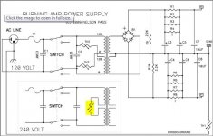
As for the protection (see picture), will be building 230V version:
-I will fuse the mains (1.25A slow blow)
-I will fuse between the psu and amplifier modules, what fuse should I use here?
-thermistor between primaries of transformer, what thermistor to use?
-thermistor from chassis to mains ground, what thermistor to use?
-I also see 2 capacitors on the schematic, why are they there (and why also before the switch?), what type and values should I use?
-any more protections needed?
Anyway, I look forward to your advice. Regards, pieter
I am going to build an M2X amplifier, I am putting together a bom for the PSU.
I found these capacitors recommended in the thread:
SLP223M035H9P3 Cornell Dubilier - CDE | Mouser Belgique
SLP223M035H9P3Mfr.:Cornell Dubilier Aluminium Electrolytic Capacitors - Snap In 22000uF 35V 20% 105C
I will use a 300VA transformer 2 x 18V, 8 x 22000uF 35V capacitors, I will omit the input snubber and the optional PI resistors. I suppose this is a good plan?
As for the protection (see picture), will be building 230V version:
-I will fuse the mains (1.25A slow blow)
-I will fuse between the psu and amplifier modules, what fuse should I use here?
-thermistor between primaries of transformer, what thermistor to use?
-thermistor from chassis to mains ground, what thermistor to use?
-I also see 2 capacitors on the schematic, why are they there (and why also before the switch?), what type and values should I use?
-any more protections needed?
Anyway, I look forward to your advice. Regards, pieter
Attachments
You can ignore my last post, I already figured it out what components to use.
CL60 thermistors, X1 capacitor 3.3uF (found as safety capacitor in mouser).
It seems to be a much asked question, maybe include it in the build guide so people dont keep asking the question over again.
CL60 thermistors, X1 capacitor 3.3uF (found as safety capacitor in mouser).
It seems to be a much asked question, maybe include it in the build guide so people dont keep asking the question over again.
You can ignore my last post, I already figured it out what components to use.
CL60 thermistors, X1 capacitor 3.3uF (found as safety capacitor in mouser).
It seems to be a much asked question, maybe include it in the build guide so people dont keep asking the question over again.
Before you order your CL-60 thermistors, you may want to check out this thread by Mark Johnson:
Not thrilled with CL-60 inrush limiter in USA/160W Class A First Watt designs
- Home
- Amplifiers
- Power Supplies
- diyAudio Power Supply Circuit Board v3 illustrated build guide