Those are bleeder resistors, use the standard recommendations (2.2-22k, 5w iirc).
Thank you very much!
My transformer is 18 0 18 and I am measuring close to +/- 27 volts DC wrt the respective Ov at the output of the psu with no load connected.
Is this correct?
Is this correct?
OK so 18 x 1.414 should give me the DC level, that means my PSU is supplying the correct voltages. Gotta be happy with that. I do worry about power supplies.
My transformer is 18 0 18 and I am measuring close to +/- 27 volts DC wrt the respective Ov at the output of the psu with no load connected.
Is this correct?
That seems about right downstream from the pi (crc) filter. It will drop a few volts under load.
Also can you use 3 phase bridges on single phase AC? Or is there any point to doing that? I read they had lower noise and produced a smoother DC signal.
Although I won’t claim expert knowledge, I think the answer to your first question must be “no”.
2nd question - nope
A well constructed monolithic bridge rectifier, or a discrete bridge using good quality rectifiers with single phase power will pretty much do anything you may need. The parts recommend for the diyaudio psu work really well.
If you are curious about the cutting edge, do a search for “ideal bridge rectifier”.
Best of luck.
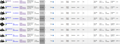
I'm struggling to choose the right spec bridge rectifier. The MUR3020 I understand is 15A and 200V. Could someone recommend one of these in the attachment?
Just not sure if going up to 400V is necessary. I was thinking:
BRIDGE RECT 1PHASE 200V 35A D-34
OR
BRIDGE RECT 1PHASE 200V 25A D-34
Thanks.
Just not sure if going up to 400V is necessary. I was thinking:
BRIDGE RECT 1PHASE 200V 35A D-34
OR
BRIDGE RECT 1PHASE 200V 25A D-34
Thanks.
Attachments
Chuckd,
I prefer discrete rectifiers, but many people like the monolithic units. They all perform well. The blocks are especially nice if you have space constraints in your chassis - they are so small - definitely a plus.
I think that the GBPC3504 (35A, 400V) is a good unit. If going with discrete rectifiers I have used the FEP30DP and it works well.
For the dollar difference involved, I would go with the higher spec part (400V) every time, although I've noticed that Vf can increase for the higher voltage parts. Try to select a piece with lower rather than higher Vf. This will leave you more potential on the rails of your amplifier.
-Keith-
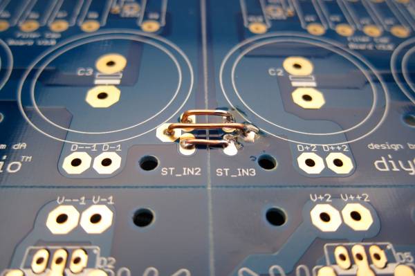
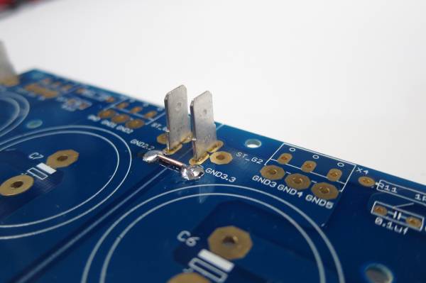
From looking at your grounds i see the jumpers at the diode end (st_in2 and st_in3) joined then at the other end of the board i see gnd2.2 and gnd3.3 joined.You have created a ground loop,the st_ end shouldn't be connected,only the gnd2.2 and 3.3 end should be connected and that is where the ground star point is taken from ie: to cl60 then power cord ground as well as to the board grounds.
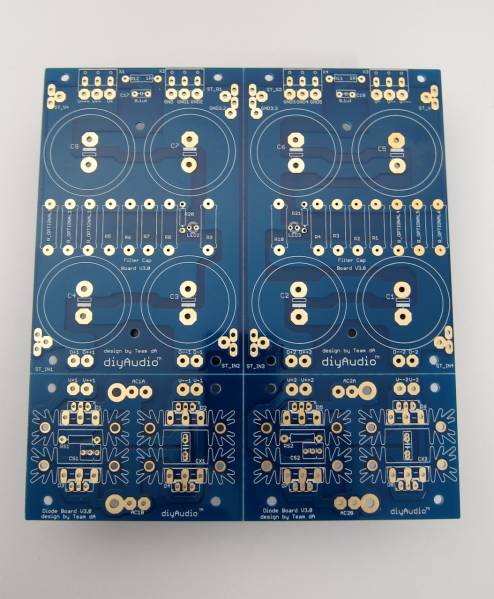
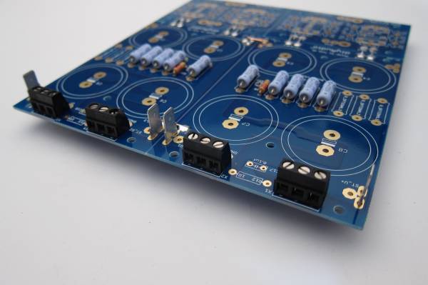
diyAudio Universal Power Supply Circuit Board v3 illustrated build guide. (October 2013)
(Any photo with a link directly below will go to full-size file of the photo)
This build guide will show a typical use of the diyAudio PSU v3 circuit board. This specific build will be suitable for any of the Pass/Firstwatt amps that use a +/-25V supply. If you need a higher voltage make sure you use capacitors of a suitable voltage rating for your project. You may always have a higher voltage rating, but do not use a cap with a lower voltage rating than your rails.
Useful Links
BOM - http://www.diyaudio.com/forums/images/diy/store/board-documentation/P-PSU-1V30/P-PSU-1V30-bom.xls
Schematic - http://www.diyaudio.com/forums/imag...mentation/P-PSU-1V30/P-PSU-1V30-schematic.pdf
PSU18 - My Photo Gallery
((Do not connect 2-leg TO-220 diodes as shown. See photos in 'heatsink' section.))
PSU36 - My Photo Gallery
Fully stuffed
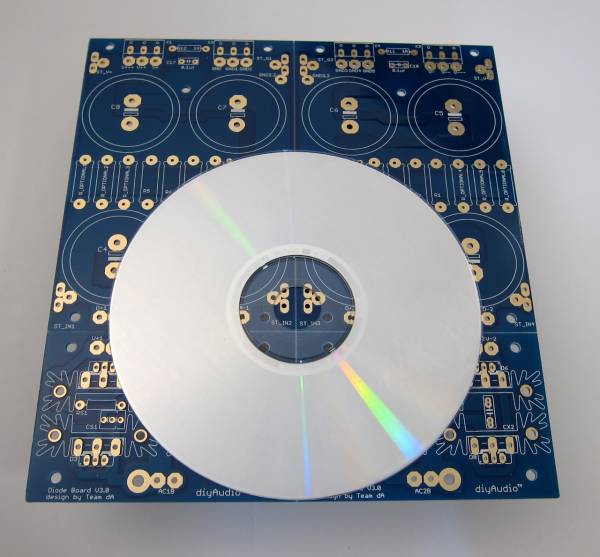
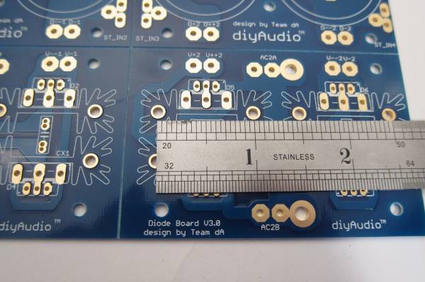
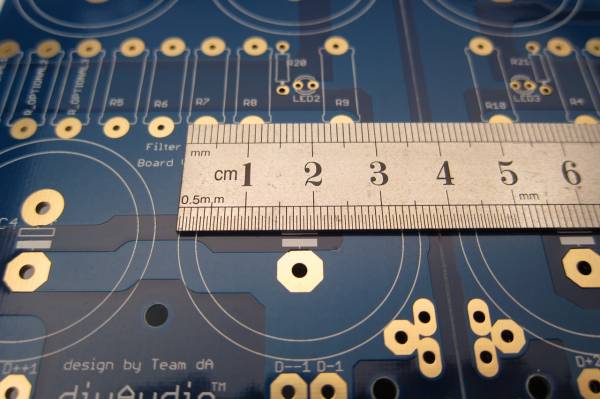
PCB scale
Dimensions -
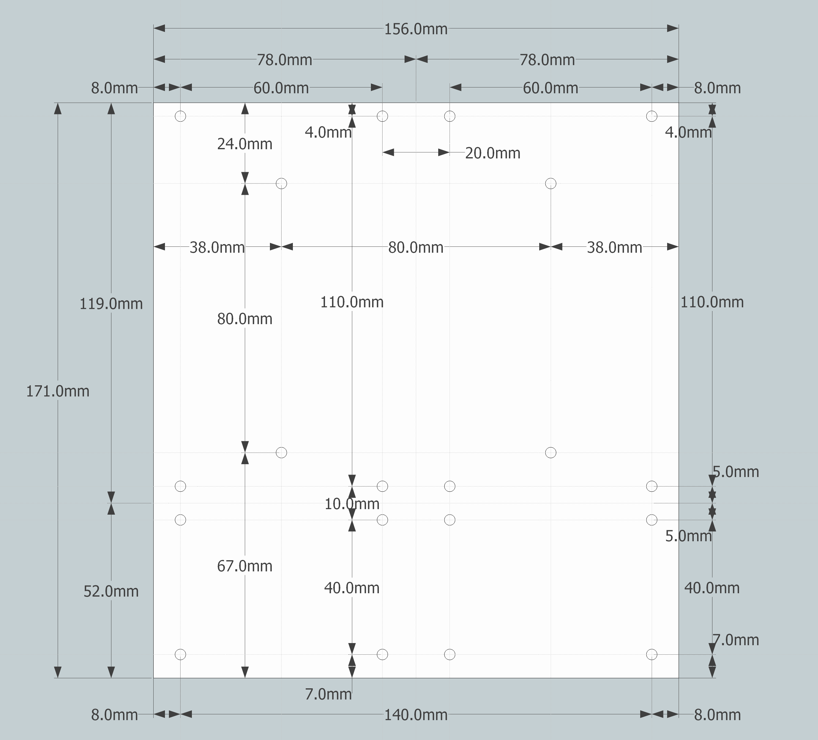
PCB dimensions

PSU14 - My Photo Gallery
The heatsinks are one inch post spacing. Look at the BOM for a specific part suggestion and find something similar that you can use. The sinks I used in this guide are of the same outer profile, so they fit the pads perfectly, but are quite a bit taller. A number of parts will be available that will work.
IMG_2134 - My Photo Gallery
This board can accept capacitors of up to 35mm diameter.
IMG_2136 - My Photo Gallery
Equally important is the lead spacing - the caps should be 10mm 'snap in'. 10mm radial leads will work as well, but usually the bigger diameter caps have the 'snap in' leads.
For more information on dimensions of the specific parts, please consult the BOM for suggested parts, and cross-reference from that part's datasheet. http://www.diyaudio.com/forums/images/diy/store/board-documentation/P-PSU-1V30/P-PSU-1V30-bom.xls
Board features -
The bridge diode section of the board can utilize either TO-247/TO-3P (larger) package devices or TO-220 (smaller). If heat dissipation / heatsinking is not an issue, you could also use conventional axial-leaded diodes. (Not shown.)
IMG_2135 - My Photo Gallery
If you would like to use snubbers on the rectifier diodes you will find that there is room for them on the top of the PCB, and inside the heatsinks.
IMG_2141 - My Photo Gallery
If you don't find enough room there, or would like to try a different snubber layout, there is plenty of place to connect on the bottom of the PCB, as you will always have one of the d=sets of diode pads empty - you can only use one type of diode at a time, for example if you are using the TO-220, the TO-247 pads will be empty and you may make connections there.
IMG_2142 - My Photo Gallery
For designs that require one, there is also room for a snubber on the output. (Per rail)
Also worth noting, in this photo you can see the multiple solder pads for the output - the row towards the edge is for the euroblock connectors, and the inner row, with the larger pads, for wire. There is also a place for a blade terminal. (Near the board edge, on the outside. To be better illustrated in a later photo.)
Building / Stuffing
PSU41 - My Photo Gallery
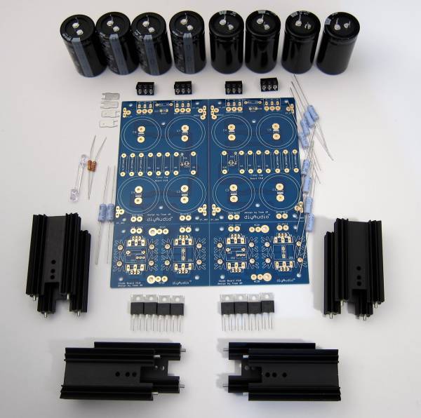
This photo shows all the parts that will be used in this guide.
Starting at top and circling clockwise -
Capacitors and 'euroblock' connectors
(8) filter or 'pi' resistors
Diode heatsinks and diodes (TO-220 package shown)
(2) bleeder resistors
LED and LED resistors
AMP terminal blades
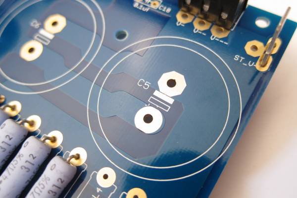
As this board has the scoring to let you separate it if you so choose, you need to notice that there is no connection from the diodes to the first capacitors nor across GND. These must be connected.
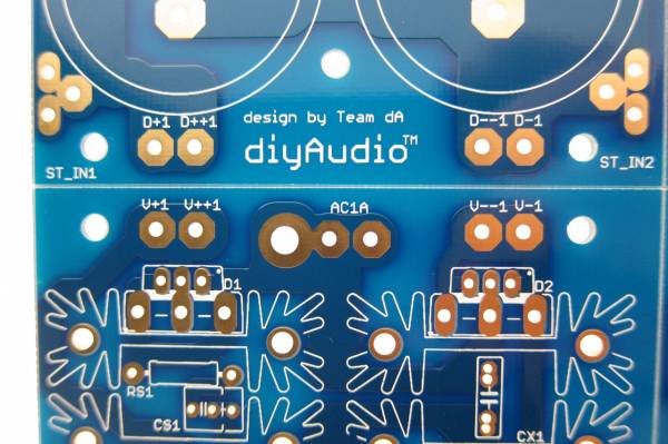
The PCB has no connection from diodes to capacitor.
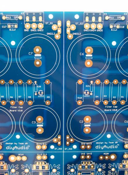
The PCB also has no connection to make GND.
Since I am planning on keeping this PCB intact for the amp I am building, I need to make a connection form the diodes to the capacitor bank, and a connection to establish ground.
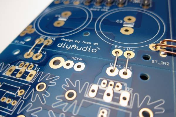
You can see all the links here (diode links not soldered in this photo)
GND links. The pads on most of this PCB are all through-plated and big enough to solder from the top if you choose.
PSU28 - My Photo Gallery
In general stuffing should be from the smaller devices to the bigger devices, so the resistors and such should be first. The filter resistors are on the outside, then the LED and LED resistors (the small brown one) and inboard are the bleeder resistors.
The silkscreen markings at the LED pads are slightly obscured, and the break in the circle, indicating where the flat of the LED should go (cathode, negative, short leg) is a little bit confusing. The legs of the LED go as shown. You can also see another link at the top of the PCB where I joined GND together.
The blades are actually taller than the euroblocks, so don't solder them first!
PSU27 - My Photo Gallery
The output edge shown with all the connectors in place
Capacitors -
As mentioned before, this PCB can accept caps with 10mm lead spacing and up to 35mm diameter. This photo shows 35mm caps next to 30mm. You will also commonly find some appropriate values in 25mm diameter.
PSU32 - My Photo Gallery
The addition of the large solder pads has obscured the markings on the PCB and the ' + ' mark is somewhat hard to make out. In each case the Positive side is marked with the open rectangle and the negative the white or filled-in rectangle. Remember that electrolytic capacitors are usually only marked on the Negative side.
PSU9 - My Photo Gallery
Note capacitor direction - you can see the negative markings on each capacitor.
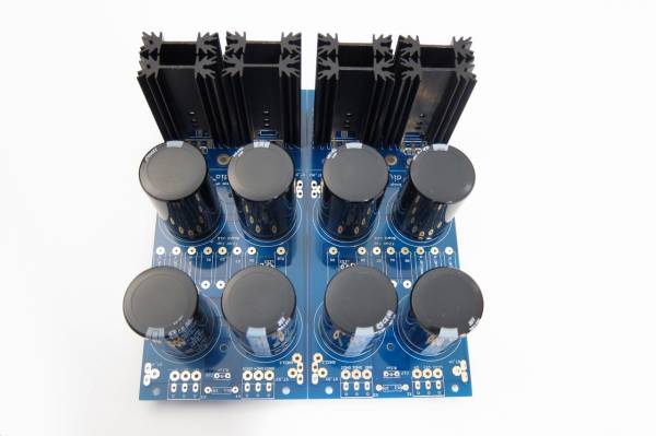
Heatsinks -
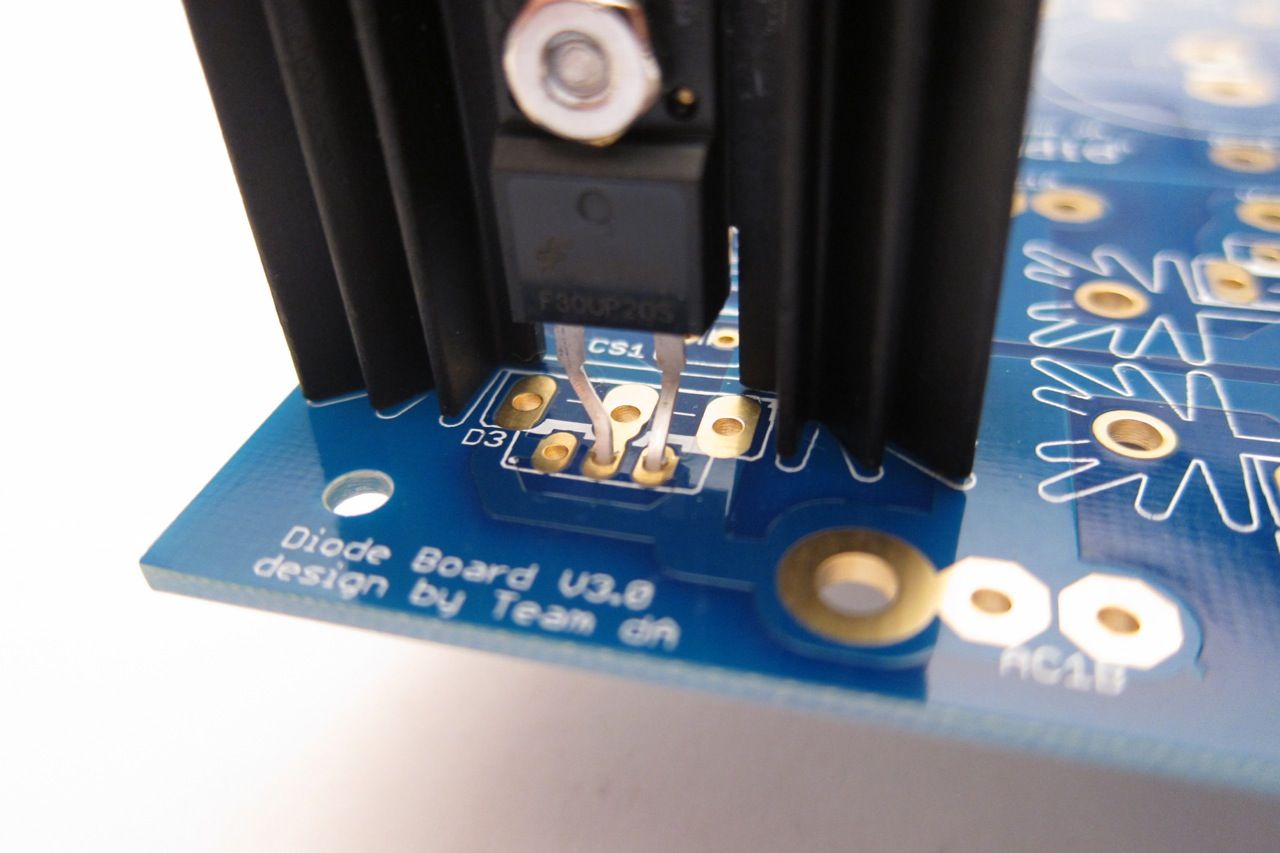
The heatsinks used in this guide were chosen as they were of proper dimension to fit the PCB, and in-stock at the time I ordered them. They are a little tall, but as Nelson Pass says, there is no such thing as too much heatsink… I do suggest you try to get something that will fit a TO-247/TO-3P package as it will also mount the TO-220, whereas the slightly narrower inner profile of this heatsink will only mount the smaller diode. Regardless, it's quite easy to get really nice, suitable diodes in whichever package - you want 30A, 200V minimum diodes.
A little grease is helpful on the full-pack devices. Secure to the heatsink with a nut and screw. This is a 4-40 screw, about the same size as M3.
Please Read - If you use a conventional TO-220 diode or TO-247/TO-3P it's a very good idea to use an insulator between the device and the heatsink. But it's not necessary - although if you choose not to the heatsinks will probably be live. The heatsinks themselves solder to the PCB and are in holes that have no electrical connection, and aluminum anodize is actually not very conductive, but I would still suggest using an insulator. (Or a full-pack TO-220)
Feel free to snap off the diode section and use monolithic bridges. They work and sound great!
NOTE - I strongly suggest not separating the capacitor board if at all possible. With it intact, you can run multiple jumpers (as shown) to tie GND together and have a low-impedance, and therefore quiet GND. Splitting it will complicate making a quiet circuit. FYI.

Example wiring.

Looking for a recommendation for a currently available make and model for the big filter capacitors. My build will be a M2, and I hope to try the F4 as well. There are many choices. I'm just looking for something reliable with generous capacity. I don't need to minimize costs, but I'm not looking to waste money. Thanks.
I like the Chemi-Con KMH series caps. I've used 15.000 µF (63V) in a F6 PSU, which i later upgraded to 33.000 µF (35V).
https://www.europechemicon.de/wp-co.../Snap-in UCC/KMH-series-Catalogue-8-2014L.pdf
They are rated to 105 degrees and reasonably priced.
https://www.europechemicon.de/wp-co.../Snap-in UCC/KMH-series-Catalogue-8-2014L.pdf
They are rated to 105 degrees and reasonably priced.
10mm snap-in leads, no greater then 35mm diameter, minimum 25v, value between 15000-22000uF . Bigger value is not necessarily better, although bigger can size usually has lower esr and more ripple rating. 105c rating is beneficial for longevity.
Looking at Mouser stock right now, these look great - B41252A7189M000 EPCOS / TDK | Mouser. The NCC that Silas linked to above are also a great suggestion.
Looking at Mouser stock right now, these look great - B41252A7189M000 EPCOS / TDK | Mouser. The NCC that Silas linked to above are also a great suggestion.
Last edited:
They look great, do check the snap in lead spacing.
I would buy enough to fill the board (8?) and as they are large around 140,000uF in total you will definitely need some form of soft start. I can't remember what the required ripple current rating was for my f4 but it wasn't out the ordinary, when you find a cap you like the look of, check it against a bunch of others and make sure it doesn't seem abnormally low.
I would buy enough to fill the board (8?) and as they are large around 140,000uF in total you will definitely need some form of soft start. I can't remember what the required ripple current rating was for my f4 but it wasn't out the ordinary, when you find a cap you like the look of, check it against a bunch of others and make sure it doesn't seem abnormally low.
A practical question:
I have heatsinks in similar size as in at the picture (from the guide). When heatsinks are mounted (soldered) into place how to mount the diodes using screw and nut? ….not much space between heatsinks to get a screwdriver in between?
How to solve this is not shown in the guide in this thread?
Maybe to have the nut at the backside could be a solution and then use a pincet to hold the nut to get it on the screw and after then a small wrench to hold contra. Any other suggestions?
Attachments

An externally hosted image should be here but it was not working when we last tested it.

If you don't have similar tools, stuff and secure the row of diodes closest to the AC inlet first, then the same with the next row, then the capacitors. You don't need special tools if you assemble in order.
Hey MEPER. I would attach the diodes to the heatsinks before soldering anything in place and hold them in place with some tape while soldering.
- Home
- Amplifiers
- Power Supplies
- diyAudio Power Supply Circuit Board v3 illustrated build guide