Ok......thank you!
I don't have the special nuts…..what is the name of those?
They "bite" then touching the heatsink?
I think I should also be able to change a diode when all is assembled…..if one of the diodes fails during operation.
I don't have the special nuts…..what is the name of those?
They "bite" then touching the heatsink?
I think I should also be able to change a diode when all is assembled…..if one of the diodes fails during operation.
Hmmm... I thought SOP was always to attach the part to the heatsink before soldering so that attaching doesn't put undue stress on the solder joints...?
I am with you JeffYoung, that was my impression as well.
MEPER, i believe the nuts are called kep nuts, but i havent found the danish name. Tubeampdoctor sells them, but they are pricey.
As for the caps, ask Jensen and compare it to industry standards.
MEPER, i believe the nuts are called kep nuts, but i havent found the danish name. Tubeampdoctor sells them, but they are pricey.
As for the caps, ask Jensen and compare it to industry standards.
My intention is to mount heatsinks first (they are soldered to PCB). Then I will attached the TO-220 diodes to the heatsinks with screw and nut and after that solder the diodes. The problem is when all four heatsinks are soldered that there is not much space to mount diodes. I could mount diodes first on each heatsink and then solder heatsink and then solder diode. But I should also be able to change a bad diode.
Ok......I will try to find the "kep nuts" or get them from Tubeampdoctor……..
Ok......I will try to find the "kep nuts" or get them from Tubeampdoctor……..
Kep nuts, K-nuts, Nuts with lock washer. 6#32 8#32 M3 M4 M5 M6 M8 304/201/Carbon Hex Lock Nuts Keps Nut Tooth Washer FZ | eBay
If a diode fails, what on earth are you doing to the amplifier? 😀
If a diode fails, what on earth are you doing to the amplifier? 😀
If a diode did fail, I'd clip its leads, unsolder the heatsink, and then unsolder the clipped leads.
Swap diodes, re-solder heatsink and re-solder diode.
Swap diodes, re-solder heatsink and re-solder diode.
Ok.....it should be possible to unsolder the heatsink. But maybe a problem that will never occur. The solder joints for the heatsinks are "through plated" so could be difficult with only one iron. Maybe a hot air gun can heat up both joints simultaneously.
I will get some of the K-nuts…..etc...…...thank you!
I will get some of the K-nuts…..etc...…...thank you!
I guess it would be sufficient to solder heatsink in one side only?
Then maintenance will be easier…..will see how "solid" it feels….
Then maintenance will be easier…..will see how "solid" it feels….
I ended up using isolation pads and old fashioned isolator for the 3mm screw. Then I needed to "up-drill" 3mm holes in diodes and heatsinks to 4.1mm to be able to insert isolator. In the old days holes had the right sizes? …..I refuse to use nylon screws for this task...….
I understand why people just use a diode bridges but these Cree SiC diodes are nice and wire path from diodes to caps very short which I think will give less radiated noise.
I understand why people just use a diode bridges but these Cree SiC diodes are nice and wire path from diodes to caps very short which I think will give less radiated noise.
Attachments

A practical question:
I have heatsinks in similar size as in at the picture (from the guide). When heatsinks are mounted (soldered) into place how to mount the diodes using screw and nut? ….not much space between heatsinks to get a screwdriver in between?
How to solve this is not shown in the guide in this thread?
Maybe to have the nut at the backside could be a solution and then use a pincet to hold the nut to get it on the screw and after then a small wrench to hold contra. Any other suggestions?
I installed my diodes on the heatsink before the heatsink was installed on the board. I had no issues using this method.
Regards,
Dan
Yes, I will be doing the same. I am preparing 16 diodes + heatsinks for the two PSU boards. It just takes a little time bending legs etc.....to ensure a proper fit. But quite relaxing mental job. 🙂
You can get the isolator tabs and inserts in either metric (M4) or imperial (#6 machine screw, which is about 3.3mm).
Cheers,
Jeff.
Cheers,
Jeff.
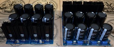
The isolator I used was made for 3mm screw and hole needed to be drilled 4.1mm in both diode and heatsink and for the isolator pads I used a tool for making holes in leather belts to make the hole a little bit larger so isolator for the screw could fit. All 16 diodes are now mounted on heatsink and ready to be installed. I have tested that all diodes are electrical isolated from heatsink. I like that even that it is not strictly necessary.
Attachments
+1.Hmmm... I thought SOP was always to attach the part to the heatsink before soldering so that attaching doesn't put undue stress on the solder joints...?
To change diode - we have to unsolder heatsink first.
Last edited:
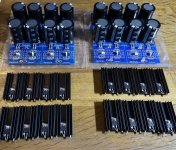
Normally I would install heatsink first and solder it in place and after that install the diode but due to very little space on PCB for mounting I did it as above picture shows. It would have been nice if diode just fit into holes on PCB without bending legs. Seems most of these TO-220 diodes has pin1 = Cathode (case) and pin2 = Anode?
So...….now finished and a very quick function test is performed to see that components works as expected…...caps gets right voltage etc. Next step is to solder components into Pass MX2 amplifier boards. I made two PSUs as I build mono blocks. Power supply build is often the most time consuming of such a build.
Attachments
Hi All,
I've read through the thread and the BOM end to end. As always, thanks to 6L6 and everyone else for helping make it possible and maybe even practical for me to take the next steps in DIY.
I have a few quick questions. I searched for answers to all of them, but if I missed anything, I'll happily re-read. I'm still at the stage where it takes me days to cross-reference a BOM and choose parts b/c I am still learning what all the specs mean, and rarely know which specs are the critical specs. The flexibility offered to seasoned builders often trips me up. But, I learn along the way. Your help and patience with a newbie is appreciated.
My goal with the power supply will be to build one that will serve as many First Watt projects as possible while changing no (or few) parts. I will be using the Antek AS-4218. I may be housing the PSU in a separate enclosure from the amp or moving it after the first build is up and running properly. I'll be building the M2X and the various daughter boards.
Questions.
1) Diodes - In my notes I have (from the build guide) to chose "30A, 200V minimum diodes." Note 4 in the BOM clearly states that the diode reverse voltage is based on the transformer secondary voltage rating. The secondaries are 18V on my model. I can't find any kind of "rating" in the spec sheet. http://www.antekinc.com/content/AS-4218.pdf
I always love the recommended parts in the BOMs - there is no way I could do this without them. The diode in the BOM (625-FEP30DP-E3) has a reverse voltage max of 200V. I'd assume that is gracious plenty for all the First Watt amps built with the Antek transformer I've chosen, correct? I ask because I don't love desoldering, particularly parts with heatsinks. So, if I can put in a more robust part for a bit of extra money now, I will. Even this one seems "overkill". Any guidance or confirmation if I am reading the "correct" segment of the specs is appreciated and interpreting the note properly. I found this 300V one (and ones with even higher voltage ratings with identical specs). VS-30CPH03PBF. Is there any valid reason to use a higher rated one? It's trivially more expensive when looking at the cost of the build. If it helps to potentially future proof it, I can put them in. I feel like I'm looking at the wrong spec.
2) The input snubber. I am still wrapping my head around what a snubber does. The Hagerman article was extremely helpful, but way over this newbie's head. For now, I'll ask simply if they can do any harm (if the value is properly calculated) other than adding a bit of cost to the build. I've read as much as I can absorb for now about whether they're strictly needed, but I as yet, haven't found a good reason not to use one. Again, if for SOME amps they are actually needed, I'd prefer to add it as long as there's no harm done other than to my wallet. I know this is a hotly debated topic, but is there any reason other than cost to not add it? My inclination at the moment is that I want to put it in (to help future proof for amps where it may be needed), but there's no way in the world I can calculate the right value. I'm holding off for now. I don't even know if the value that should be used depends on parts outside the power supply itself. If there's a strong opinion to put it in, I'd be grateful for help.
3) Caps. It seems more is better. Other than one's wallet, it seems this is one part where you can go nuts and not hurt anything, while maybe helping and future proofing. I tried to find 10mm lead spacing, highest voltage rating, highest capacitance. There was a 15k model at 50V that was not listed as "audio", so I found these. LKS1K103MESC They specifically note for audio use in their specs. I could be getting taken for a ride, since it seems all sorts of products are labeled "for audio", but Nichicon seems to be an oft-used brand. Any concerns from the group?
4) Resistors - "If CRC filtering is not required..." - Well, again as with snubbers. I get lost. Since they are clearly in the pics in the build guide. They go in. For the LED Dropping resistors, I went with 10k. I picked the exact LEDs in the BOM. For bleeders, I went with 22k. It says go higher for higher voltages, but I am assuming that 22k can't hurt even if it's too much. Any concerns?
WHEW! After a week + of reading, my final BOM is ready to upload Mouser (unless I bombed)... 🙂 I went there... It feels pretty good.
For capacitor voltage select the lowest voltage that is a safe distance from working voltage of the PSU. So for a 24V PSU then 35V should be safe (if cap is from a well regarding company). Then you get more uF for the money. You can get 33.000 uF / 35 VDC caps that fits the board. The PSU board is designed for CRC....so why not use it? …...it may give you a factor 5 to 10 ripple reduction. To use diodes (as I did) instead of a bridge take a bit more patience and time to get everything mounted. But you get a very tight coupling between diodes and caps which is good (if you also have short wires from transformer to PSU boards). For the snubbers I took the "easy path" and looked what others used knowing that it will not be a perfect match. To make a perfect match you need to know all parameters of your transformer and diodes. Think I used 100nF and 100 ohm. Worst case is that it will have no effect. The idea is to take some of the energy out of the transformer choke during switching to reduce ringing.
1. Diodes, I used separate diodes in my first build. For what it's worth, I would probably go with one of those big monolithic Bridge rectifiers next time. Reason being was filing the heat sinks to fit was a hassle, they take up lots of space and I'm not really convinced they'd be any better.
2. General advice and snubbers for class a amps is don't use them. If you later do a project that needs them they would be very easy to retrofit to the board in situ, just cut the leads to length and solder from the top.
3. Caps, I used 22000 35v in mine. They're more compact than 50v ones. I'm not entirely convinced of the for audio either. If they're a decent quality cap and not bargain basement they'll probably be just fine. Do have a look at the ripple current rating. If you have a look on the mouser (or whoever you're buying) page and see how they compare to other similar products. If all a muchness then they're probably OK. If they're much lower than the bulk of the ratings look elsewhere. Do go for higher temperature rating, 105 degrees or higher. They'll last longer. The class a amps do get toasty inside.
4. Crc, just go with what ever 6l6 did on his build guide. It'll work.
Led resistors are easy to calculate. Look at the data sheet and see what the leds voltage drop and operating current is, let's say 1.7v and 8ma. This means it wants the current limited to 8ma and what ever voltage you present to it, only 1.7v will get dropped. (they don't obey ohms law).
So, you know that you've got 24v rails, so assuming you have a resistor and led connected between the rail and gnd....
24v minus 1.7v led equals 22.3v across your led resistor.
You want 8ma of current so from ohm law voltage divided by current equals resistance
22.3v divided by 0.008A (don't forget to use amps not milli amps!!!!!) equals 2k7 ish. Leds usually function quite happily with currents well below the max so 10k would be fine. If in doubt use a higher value to start with, if its super dim (and having checked the rail voltage is what you expect) you can always lower the led resistor if need be.
You then just want to check that youre not going to melt your resistor so use I squared R.
0.008A*0.008A*2700ohm equals 0.173W so you could use a 1/4w resistor here. Although I would use a 1/2w if I had one.
- Home
- Amplifiers
- Power Supplies
- diyAudio Power Supply Circuit Board v3 illustrated build guide