

Honey Badger don't give a darn.. 🙂
He can take care of predators moving in on his audio turf.
He can take care of predators moving in on his audio turf.
Last edited:
And I'm measure speaker output and speaker gnd.
Reading around 1XmV to 1mV. Is it normal ??
That is normal ... as I said before R53/54 burn with no fuses ! Andrew T. suggested these and they have merit.
I do it different and just build up to the driver stage with 2 10R "sacrificial"
resistors on the rails before I go about "stuffin" outputs. Emitters of the drivers will be
+/- .6V with 2 68R's connected temporarily to the output coil.
NEVER a smoked output have I made (yoda speak 😀) .
To keep the Badgers "clean", consider "floating" R23
,27,32,33,36,37-41,50,53,54 slightly above the PCB or use "flameproof" devices.
OS
^ 
i make it a practice to lift all resistors off the boards by at leas 1/16 inch in all my amplifier builds, more clearance for high powered ones....
i make it a practice to lift all resistors off the boards by at leas 1/16 inch in all my amplifier builds, more clearance for high powered ones....
^
I make it a practice to lift all resistors off the boards by at leas 1/16 inch in all my amplifier builds, more clearance for high powered ones....
Best to keep "COOL". I also use 100R for R27 , this will set the VAS current source for 5+ mA (very cool).
This will not affect the compensation of the amp in any way. The Vbe resistor (R29-680R) will need to be changed to 560R to give
the same range for "Vbias" (R30).
OS
I have a lot to read into this lot of info, maybe there is going to be one Honey Badger in
Puerto Rico soon
Regards
Juan
Puerto Rico soon
Regards
Juan
OS I just need clarification as I am checking all the updates. In post 1036 page 104 you have the 12V zener and C6 going to earth G2.
On the original circuit diagram they go to R16. Am I missing something?
Can't wait for the new PCB's!🙄
On the original circuit diagram they go to R16. Am I missing something?
Can't wait for the new PCB's!🙄
OS I just need clarification as I am checking all the updates. In post 1036 page 104 you have the 12V zener and C6 going to earth G2.
On the original circuit diagram they go to R16. Am I missing something?
Can't wait for the new PCB's!🙄
Yes ! The new PCB will have the C-Z jumper as default (Z goes to G2-small signal ground).
With the R , you could reference it to EITHER the "virtual" ground of the LTP (.7V - AKA "luxman way") or to the same hard ground as "Z".
Options will still be available but a "build it this way or die" 😀 is on the
screenprint (below).
Will be PMing Variac with this "final".
I just stuffed my boards (below 2), I know of NO lead space or hole issues.
Still need parts , not too economically secure. 😱 More E-waste ! 😀
OS
Attachments


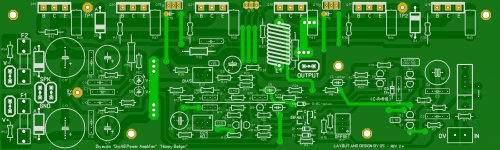
Well, moving mounting hole, C11, C12 and C13 to the right would unblock space in front of SPK GND and euroblock could be used. Anyway, there would be more space around this terminal so connecting cables would be easier.
cheers,
cheers,
Ostripper,
That's a good looking layout! You've convinced me to order up a few boards.
That what I want to hear ... then this is the one that goes to Variac tonight.
I'll look over any fine points (45 degree angles + no sharp turns on corners).
Look over the screenprint for "ease of construction".
This layout has uniform .6mm+ spacing ,as well ...(UL 60950-1 Table 5B compliant
-DC voltages).
I thought hard on Q13 (Vbe device). For this circuit , the Cob of the devices
would "swamp out' any trace capacitance and having the Vbe cap (10-22uf)
real close to the jumpers virtually eliminates inductive issues (positive rail /output currents).
This style layout = EF2 only !!
A layout like this would not be ideal for a triple output. Any capacitance or inductive feedback
would degrade performance.
I must say
 , after assembling my Badgers, I was able to export the real world
experience to the upgrade in the layout. Still , the V2.3 board is more
professional looking and adheres to stricter design standards than just about
all the OEM amps I have ever repaired.
OS
Hi OS ,guys
I find the questions of my band.
The question is Q14,Q15.
I use TOSHIBA 2SC4793/2SA1837(F,M),it's bad in this band.
And I use onsmi MJE15032 / MJE15033 ,it's OK😀
I find the questions of my band.
The question is Q14,Q15.
I use TOSHIBA 2SC4793/2SA1837(F,M),it's bad in this band.
And I use onsmi MJE15032 / MJE15033 ,it's OK😀
Hi OS ,guys
I find the questions of my band.
The question is Q14,Q15.
I use TOSHIBA 2SC4793/2SA1837(F,M),it's bad in this band.
And I use onsmi MJE15032 / MJE15033 ,it's OK😀
2sc4793/2sa1837 are ok. That's what C18-c19 are for (high Ft driver).
Mje15032/33/34/35 are ideal and have higher current.
Both are OK.
OS
2sc4793/2sa1837 are ok. That's what C18-c19 are for (high Ft driver).
Mje15032/33/34/35 are ideal and have higher current.
Both are OK.
OS
OK!
OS
Thank you for your help😀
- Home
- Amplifiers
- Solid State
- diyAB Amp - The "Honey Badger"