Hi Janusz, Kay, Tony,
I put 0.47r in for the output emitters, and it helped stabilize the amp.
I currently have a resistor in for r18, but have 15v zeners on the way. They are just installed in the v2.4 board, as the board is setup. I did not change the circuit in any way. (does that mean they are not grounded?) Good channel is setup the same way.
With the .47r resistors in place, bias settles at about 30mv. (I have fixed 300 ohm in for r30).
Voltages at bases of q1 and q2 are much closer now at -112mv and -89mv respectively.
There is high likelihood that I have highly mismatched output devices from bungling along.
My dc offset is not as stable as in the good channel. The good channel was easy to set at 0.5mv, while the good channel fluctuates slightly between 2.8mv and 3.5mv.
AC voltage at output is steady in both channels at basically 0.
I don't think the drivers are oscillating, as base voltage at the outputs is steady.
I think the .47r emitter resistors helped to stabilize, but did not solve the underlying problem.
Janusz, I like the look of that test, I will give it a shot. Would be great to narrow this down, and it looks like that test would locate the problem on one side or the other. c6 fwiw, is a wima (red guy per bom). I have suspected this part in the past, and substituted a replacement but it did not resolve the issue.
As it sits now, putting a signal through the bad channel sounds good, and looks good on the scope. I'm out for the next few days, but on return will get back at it.
I made some changes to my power supply, I originally had my cap board assembled with CRC, but the R is not needed for AB amps as I understand it. So I pulled the 0.47r resistors from there and put them in for the emitter resistors.
I am now running my output grounds directly back to the star ground at the PSU.
Any recommendations on a device to test Hfe of transistors so I can learn to match my own?
Thank you all, your help is greatly appreciated.
Last edited:
Really? As increased balancing resistors' values yields to increased local NFB, I'd expect quite the contrary 😕?
Best regards!
an emitter follower with re is 100% negative feedback, increasing collector current increases voltage drop across re, so that Vbe is decreased and the trannie becomes less conductive, i.e. transconductance goes down.... in an rca handbook i even saw 1 ohm resistors being used for re...bipolars become more conductive as they heat up...this has been well known as early as 1960...
Any recommendations on a device to test Hfe of transistors so I can learn to match my own?
Rod Eliott rigged this test setup for power devices....hFE Tester for NPN Power Transistors
I see that bigger Re values increase the transistors' output impedance, as any current NFB does, but not their transconductance really. But I still don't see why THD would be increased by that. Compare with tube circuitry: Unbypassed cathode resistors are well regarded as local NFB, not as some mean to increase THD.an emitter follower with re is 100% negative feedback, increasing collector current increases voltage drop across re, so that Vbe is decreased and the trannie becomes less conductive, i.e. transconductance goes down.... in an rca handbook i even saw 1 ohm resistors being used for re...bipolars become more conductive as they heat up...this has been well known as early as 1960...
Best regards!
for small signal applications gm = 1/re, ie(in ma)/26mv at 25 *C, i am not so sure about large signals but i believe they should be the same...
as to how it increased distortions i do not have the mathematical explanations but i go by the opinion of gurus.....
years ago, there was a discussion about the optimum drop across re for good distortions....John Curl commented on it as i recall...
with tubes the cathode currents determine tube transconductance, and in series with cathode resistors that are not bypassed, made the overall stage transconductance lower.....i think it is the same with transistors...
Last edited:
Wouldn't the increased voltage required to overcome the higher resistance also increase crossover distortion?
Hi Janusz, Kay, Tony,
I put 0.47r in for the output emitters, and it helped stabilize the amp.
I currently have a resistor in for r18, but have 15v zeners on the way. They are just installed in the v2.4 board, as the board is setup. I did not change the circuit in any way. (does that mean they are not grounded?) Good channel is setup the same way.
With the .47r resistors in place, bias settles at about 30mv. (I have fixed 300 ohm in for r30).
Voltages at bases of q1 and q2 are much closer now at -112mv and -89mv respectively.
There is high likelihood that I have highly mismatched output devices from bungling along.
My dc offset is not as stable as in the good channel. The good channel was easy to set at 0.5mv, while the good channel fluctuates slightly between 2.8mv and 3.5mv.
AC voltage at output is steady in both channels at basically 0.
I don't think the drivers are oscillating, as base voltage at the outputs is steady.
I think the .47r emitter resistors helped to stabilize, but did not solve the underlying problem.
Janusz, I like the look of that test, I will give it a shot. Would be great to narrow this down, and it looks like that test would locate the problem on one side or the other. c6 fwiw, is a wima (red guy per bom). I have suspected this part in the past, and substituted a replacement but it did not resolve the issue.
As it sits now, putting a signal through the bad channel sounds good, and looks good on the scope. I'm out for the next few days, but on return will get back at it.
I made some changes to my power supply, I originally had my cap board assembled with CRC, but the R is not needed for AB amps as I understand it. So I pulled the 0.47r resistors from there and put them in for the emitter resistors.
I am now running my output grounds directly back to the star ground at the PSU.
Any recommendations on a device to test Hfe of transistors so I can learn to match my own?
Thank you all, your help is greatly appreciated.
In older version if you choose resistor instead of zener it's not grounded. I guess the same happens in ver 1.4 - see the first attachment. Resistor goes to the collector of Q7.
cheers,
I did check my use of the jumper, and I am using the grounded configuration. I put the amp back into service, and it played nice and cool for an hour and a half yesterday and sounded good. I will pull it back apart to continue troubleshooting next week when I get home. Off to Idaho for a long weekend.
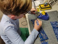
Yep, will switch back to the zener reference voltage soon. In the mean time, the 8 year old has been on my case to let him do some soldering the last couple of weeks, so he has done some, and I decided a little while ago to build another set, and let him do most of the soldering. So here he is hard at work. He's gotten pretty good at the resistors, the big diodes are a little tougher, but he is getting it...
Attachments
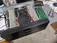
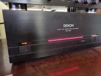
So while the boy solders up the next set of HB boards, I am thinking about a home for them. I have decided to sell my denon poa2200 amp, as the existing honey badger sounds significantly better. I got the Denon used cheap, as it didn't work, but a couple new outputs was all it needed. But I got to thinking, the Denon would make a PERFECT home for some honey badger boards. It has a huge transformer, has huge long heatsinks, and it looks like it would be pretty close to a drop in. Just drill the heatsinks for the HB, and intsall... The rails are +-72V and it has 4x10,000uf filter caps for each channel. Power supply is split into two after the transformer, effectively giving it dual mono construction (shared transfo though). I can't really think of a reason why this wouldn't work...
Here is what the denon looks like with it's clothes off...
Here is what the denon looks like with it's clothes off...
Attachments
Last edited:
Don't underestimate the time and cost of purchasing and machining an enclosure.
Using the Denon will save you money and time but really depends on your goals.
Do you want the satisfaction of building an entire amplifier from scratch including case or are you happy with recycling?
If it were me having built several amps now, I'd be tempted to recycle the Denon and maybe replace the power supply caps depending on age
i will never hesitate to use that Denon casing and psu parts, you can also be inventive and change the trademark label and stuff, that is fun...... 😀
Summitp it is great to see your son working on his Honey Badger. The Denon donor chassis looks like a good fit and I think ostripper would approve.
Last edited:
Thanks longspeak. Thanks for those bits, gonna toss em in the boards after overtime ends in this hockey game. Pulled the Denon ad. It's going to become... The D-Badger!

Yep, will switch back to the zener reference voltage soon. In the mean time, the 8 year old has been on my case to let him do some soldering the last couple of weeks, so he has done some, and I decided a little while ago to build another set, and let him do most of the soldering. So here he is hard at work. He's gotten pretty good at the resistors, the big diodes are a little tougher, but he is getting it...
Please,do not allow children to inhale smoky solder fumes!
- Home
- Amplifiers
- Solid State
- diyAB Amp The "Honey Badger" build thread