So on my honey badger channel that was having stability issues, I think I have it resolved. Originally at inputs q1 and q2, I had a pair of mpsa18 in there. I swapped them out with mpsa06 that were bulk, not cut tape, and the issue persisted. I put the mpsa18 back in. I found that occasionally the issue got better on q2, mv dropped to same as good channel (still large variance to mv base q1), but sometimes not. Traced that issue to a questionable solder joint on r6. But the mismatch in base voltages between q1 and q2 persisted, and I would see oscillation on the scope at 1000hz when volume was raised. So problem not solved. I has some cut tape mpsa06, so I grabbed two off the tape and put them in, bam, problem solved. Mv at base q1 and q2 was now very close, bias stable, and DC offset stable at 3mv (would move up and down +-0.1mv.). No more oscillation at any frequency, all the way up to max volume from the preamp. Tested output on the scope on both channels at max volume, and all looked well. Tested with a speaker, all good. Closed it up, back in the living room. Listened to some leftover salmon for a while, then put on the hockey game, and then some chick correa. All sounded very nice, and amp barely got warm. Bout 2.5-3 hours of play time. I appreciate the help from everyone here. Thank you! I'll keep you posted if that one acts up again.
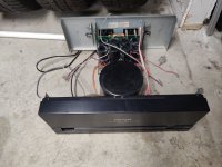
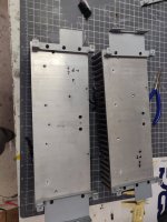
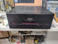
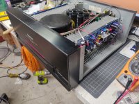
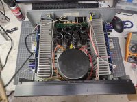
I also made a little headway on the D-Badger. The boy finished soldering up the boards. On the donor Denon, I pulled the original amp boards out, and removed the heatsinks and started drilling and tapping some holes. What a tedious process.
I also made a little headway on the D-Badger. The boy finished soldering up the boards. On the donor Denon, I pulled the original amp boards out, and removed the heatsinks and started drilling and tapping some holes. What a tedious process.
Attachments

Last edited:
So no miracles, just faulty components. Mismatch between base voltages on LTP suggested that at least one of these transistors could be faulty. But you changed mpsa18 for mpsa06, so assuming that you checked these new transistors before replacing them, made things more complicated.
cheers,
cheers,
So no miracles, just faulty components. Mismatch between base voltages on LTP suggested that at least one of these transistors could be faulty. But you changed mpsa18 for mpsa06, so assuming that you checked these new transistors before replacing them, made things more complicated.
cheers,
That's right.
 I need to build or get myself a transistor hfe tester to check these things.
If anyone needs some MPSA18's I have genuine Onsemi ones for sale on ebay. They are the high gain one's.
MPSA18RLRAG MPSA18 Bipolar Transistors BJT NPN Low Noise | eBay
MPSA18RLRAG MPSA18 Bipolar Transistors BJT NPN Low Noise | eBay
reminds me of good times MANY years ago!
good to start 'em young, but PLEASE get a solder fumes filter for that young man!
mlloyd1
good to start 'em young, but PLEASE get a solder fumes filter for that young man!
mlloyd1
Yep, will switch back to the zener reference voltage soon. In the mean time, the 8 year old has been on my case to let him do some soldering the last couple of weeks, so he has done some, and I decided a little while ago to build another set, and let him do most of the soldering. So here he is hard at work. He's gotten pretty good at the resistors, the big diodes are a little tougher, but he is getting it...
i used the s9014 at input ltp....matched them for hFE and vbe...
I've used those same LTP's too. But it seams the higher hfe series is absolite.
One side is alive...
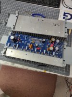
Seems to be stable, and has undergone initial adjustment to 16mv bias, 2mv offset, and 8.22v across r14. These are setup with zener diode to set the input voltage. I haven't put a signal to it yet.
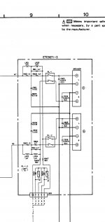
Believe it or not, I do have a question. The speaker out board on the Denon has a zobel network with a coil inductor and resistor von it already. Should I just use those (would be easiest)and jumper the zobel on the hb? Ive attached a pic of the speaker board schematic.
Speaker return ground is already routed back to star ground at the power supply. Nice.
Seems to be stable, and has undergone initial adjustment to 16mv bias, 2mv offset, and 8.22v across r14. These are setup with zener diode to set the input voltage. I haven't put a signal to it yet.
Believe it or not, I do have a question. The speaker out board on the Denon has a zobel network with a coil inductor and resistor von it already. Should I just use those (would be easiest)and jumper the zobel on the hb? Ive attached a pic of the speaker board schematic.
Speaker return ground is already routed back to star ground at the power supply. Nice.
Attachments

I also used ss9014 in my HB and also buy parts in larger quantities whenever it makes sense. Besides, one can save some money as there are always some projects in waiting.
cheers,
cheers,
Did some measuring on the completed D-Badger channel, (need standoffs to show up so I can finish the other side) and I am seeing +- 72.1v rails. I put a 60hz signal to it, and measured Vac at the output with dmm. It got to 50.1vrms just before clipping began to show on the scope. With an 8 ohm speakers, that indicates that the amp should be capable of putting out 313 watts. That sure seems like a lot. Am I making any calculation mistakes? I did 50.1^2/8=313.75. I don't have a dummy load to use when testing ac voltage output.
Inputs are mpsa18.
Output devices are mjw3281A/1302A in to-264 package.
Drivers are mje15032/15033.
Bias is currently stable at 21mv nice and cool. DC offset is 2mv stable. Voltage across R14 shows 8.25v.
Oh, any issues with the built in zobel network shown on the Denon schematic in my last post? I want to use that if I can. Jumper the zobel on the board. I would remove the coil inductor L1 and R49 and R50.
Last edited:
Due to supply rail voltage sag, output signal will clip at some much smaller level with an 8 ohms load connected.
Best regards!
Best regards!
It's alive but not without a struggle. All because of builder rusty and errors. Will not go into details or errors but both sides are now working. Clean sine wave and excellent square waves. Way over kill for my 103db horns, doubt if I am using more than a few watts but this was a project I have looked at doing for years. Slight noise on horns but goes away at 3ft but dead quite on 87db test speakers. Sounds really good with short listening session.
Nice work wdecho, good persistence. I may have missed it, have pics of your build? How did you spec it out?
a so called 100 watt amp tested using sine waves will never put out 100 watts playing music, few watts and ear splitting levels are reached....
unlike sine waves, music has far less energy content, amplitudes may reach peaks comparable to sine waves, but never enough to reach 100 watts...
if you want to verify, put a watt meter like that "kill-a-watt" to monitor, you will see what i mean...
unlike sine waves, music has far less energy content, amplitudes may reach peaks comparable to sine waves, but never enough to reach 100 watts...
if you want to verify, put a watt meter like that "kill-a-watt" to monitor, you will see what i mean...
Yeah, I was doing the math and was a bit surprised. I certainly don't expect to be listening at 300 watts. I would like to be able to measure what I build. So time to read up on testing amplifiers for actual power output. Amp is done. The Denon has a long led that has 4 different diagnostic functions, speaker impedance check, thermal protection, and l and r dc protection. All functions are retained. I just need to decide what to do about the zobels. I think tomorrow I will remove the factory zobel, and use the hb one.
Amp works, both channels setup easy peazy, and seem to be stable. Bias is set conservatively. I'll see about increasing from the 20mv it is set at now, based on how warm it gets during extended listening tomorrow.
Sounds good on the garage speaker with a little Tom Petty!
Amp works, both channels setup easy peazy, and seem to be stable. Bias is set conservatively. I'll see about increasing from the 20mv it is set at now, based on how warm it gets during extended listening tomorrow.
Sounds good on the garage speaker with a little Tom Petty!
Attachments
the higher powered amps will shine when transients in music are called for in the program material....
Nice work wdecho, good persistence. I may have missed it, have pics of your build? How did you spec it out?
Right now I have not tided the wiring up any and still have it where I can lay down the heatsinks for testing so no pictures yet. I have only tested it so far with my scope and generator and not for distortion. I will use my Arta software in the next few days to test it for how it looks on it. Not expecting any surprises but I have been fooled before. I have many Firstwatt clones and point to point tube amplifer builds under my belt but this is the first high power bjt build. Learned a lot building it and it was fun learning and diagnosing a few mistakes I made along the way. The sound appeared to me to get better after an hour or listening last night. I have found there is some truth in break in time with SS amplifiers. My TPA3255 class D builds had practically no bass on fire up and turned into the best bass of any amplifier I have after a few hours.
- Home
- Amplifiers
- Solid State
- diyAB Amp The "Honey Badger" build thread