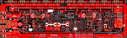
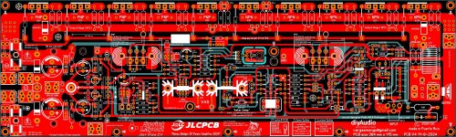
hi I wander if you guys got a simple clipping led indicator circuit for amplifier output monitoring I'm planning to add that to this PCB prototype
since this design is using the Pete's Honey Badger schematic I will post here is that okay of course 😊
since this design is using the Pete's Honey Badger schematic I will post here is that okay of course 😊
Attachments


Banned
Joined 2021
Banned
Joined 2021
Can you please share Pete's schematic?no yet
I can't seem to find it
Banned
Joined 2021

Hi vargas,I'm not gonna leave a file here because Pete mention already that this might have current loops and I haven't check 100% the layout yet it might work OK but this current loop thing got me thinking that the layout is a bad design
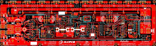
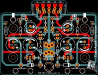
I am not a pcb expert but you have massively routed the + rail enclosing the whole circuit. I think it would be best to stick with the parallel lay-out (positive - ground - negative) scheme. Just like Oss did in the blue pcb posted above. Do not take this as a negative comment, as always your lay-out execution is beautiful.
Albert
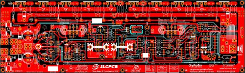
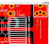
de ocampo you are absolutely right you just game an idea what about if instead of having that + long trace on the board "bottom" I would use a wire to feed the positive side the layout is already done I'm not sure if the re-done everything again after so long I even thinking to just discard this design and move on with other things 😔
Attachments
The jumper wire will work but it'll ruin your beautiful lay-out, so sorry to hear that. Has Os seen this new version that you made? I believe he has better insight of the whole circuit.
Albert
Albert
OS I don't think he will follow this and he already explain me about the ground loops problems that I might have on the design and I agree 100% of what he is saying so at least I try, sometimes you have to accepted that things can't go the way you want it on PCB designs is part of the learning process, the project "might can just work" but with a hidden ghost of GND loops and other problems but I'm not gonna gave up that easy on this 😊
- Home
- Amplifiers
- Solid State
- diyAB Amp The "Honey Badger" build thread