a so called 100 watt amp tested using sine waves will never put out 100 watts playing music, few watts and ear splitting levels are reached....
unlike sine waves, music has far less energy content, amplitudes may reach peaks comparable to sine waves, but never enough to reach 100 watts...
if you want to verify, put a watt meter like that "kill-a-watt" to monitor, you will see what i mean...
With my horns I hardly ever exceed 1 watt and even then most visitors say turn it down.
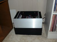
On second though to at least to prove it is real a long range shot. The big white resistor on the left side is one of my oops with a 10 ohm 3 watt resistor that smoked. Stuck a 10 wattone I had in stock in until the correct one comes in. Still a work in progress but it is alive and playing nicely. Sitting atop a FW clone.
Attachments
Last edited:
The one fault I had with this build was it had entirely too much gain for my 103db speakers. Using the FW B1 buffer with no gain I had practically no control of the volume. Just a touch open and it was almost too loud. A linestage with gain would be out of the question. This morning I decided to add some resistance to the input and first put a 10K resistor and it helped some but not enough. Right now I have 60K ohms and it is manageable. An added benefit is now the amplifier is for all intense and purposes dead quite. With all that gain I figure it must have been picking up noise from the source or buffer. Possible even the cables attaching everything. Much better now and I think I could go to 100K without any problem. For now I am going to leave it alone and try some of my tube and SS linestages. Sounds fantastic now and I general favor class A. Probably more to do with what my mind knows about class A rather than what I am hearing. But then the amplifier is probably not getting out of class A with my speakers. More to do with BJT sound vs mosfets vs tubes. There is a difference in the sound between them. Happy camper now.
Just a foot note, I thought about changing the input transistors for some with less gain but some resistance on the inputs is much easier to do and is working out just fine.
Input transistor gain doesn't affect the gain of the amplifier. It's set by the feedback resistor network (R5 & R6).
Input transistor gain doesn't affect the gain of the amplifier. It's set by the feedback resistor network (R5 & R6).
yes, input ltp/cascode gain in db, is added to the VAS gain in db and the open-loop gain is determined, now it is said that higher open loop gain lowered THD, so when you connect R5/R6 and closed the loop, that ratio will set the overall gain of the amplifier....
I'm not a big fan of inhaling solder smoke either, so we have a fan setup that blows from an open window across the work area.
i have inhaled solder smoke since age 14 also, i am now 67 and is cancer free, guess i just plain lucky...solder on....
And the sound. I am really getting into the sound of this amplifier. Quick, dynamic with great soundstage and centralized vocals. Nothing harsh sounding at all and my horns are notorious for hearing anything harsh. I am really liking the sound and only wanting to hear more from it.
I agree, the amp is fast and very dynamic. Great bass response too! I Love the way you get the fast complicated loud portions crystal clear, and when it goes very quiet on the very last notes, you can hear the quietest last drop. Very pleased with these.
i agree.....i wish someone would modify the design to use jfets at the input ltp, jfets have infinite hFE.....
I got around this morning to checking my amp some more with scope and Arta. Everything looked good on scope. Did not check when clips being that I only have 100W resistors. Noise and distortion on Arta was pretty much at the limit of my signal generator 80db from signal. I put the cover on this morning and am calling it good. Time to do more listening.
That's my version of a jfet-lateral model presented here some time ago.
cheers,
planing to make a project out of that?
Very unlikely. Genuine jfets like 2sk170 are difficult to get. Might be tempted into lateral mosfets. Have some exicons. Would have to be wired to Honey Badger boards as pin layout is different.
But I'll be building another pair of HB soon with LTP source like in this fet version. Probably will use 2x42V 625VA toroid rather than 2x45V 500VA one. Havent't decided yet. Have to find transistors for LTP, which would have sweet spot above 4mA as I'd like to make it as fast as possible. Maybe close to 60V/us. That's probably slew rate limit for this topology.
cheers,
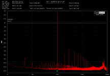
Updated Distortion Measurments
Hi Guy's
Just thought you all may like to see what this amplifier is capable of.
I just upgraded the snubber networking in my power supply using the
Quasimodo Measurement Jig to set CX, CS and RS correctly.
I'm very happy with the results so far and have a few other mods planned over the next few weeks. So I'm hopeful that I can reduce the THD and THD+N even further.
Attachments
As I see it the rail fuses are the only protection for a short to protect the speakers. I used slow blow 4 amp ones and was wondering if fast blow is what I am supposed to use. Anyone know which one I am supposed to use?
I would use slow blow for the rails and main fuse. Speaker protection of some sort would add some reassurance if you have expensive speakers.
- Home
- Amplifiers
- Solid State
- diyAB Amp The "Honey Badger" build thread