Trouble shooting guidance
Hi folks I have read the complete thread here at DYI, a ton of experience and information. Very thankful for all your experience. I have built a few amps in my time, however I am no way any shape an expert at electronics, its a great hobby for me.
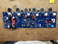
I am having issues with the Build I have the new boards 2.4 from the Dyi store bought all the parts from Mouser or DigiKey. I have double check triple checked the placement of the parts, but to no avail I have something messed up and I cant figure what it is.
When I power it up with a bulb tester, the bulb does not glow, the two leds light up. And my voltage on the 10 ohm instead of fuses goes up past 1 volt quickly, the Tp1 and Tp2 millivolts low to zero or negative.
DC offset reading from the Speaker output to ground voltage goes up as I increase the voltage from the variac, and the bulb will light as I increase the variac, but goes out as the caps charge and no adjustment will change it. When and I can start to smell a burning so I turned it off quickly.
I used all the parts from the BOM listed on the Dyi audio store site. The BOM is confusing due to the age of it in relation to the newest Sch dated 12/22/2016, some of the resistors are different there.
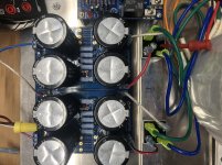
PSU is Dyi Audio board 3 with Antek 10445 dual transformer, NTE35 amp rectifiers Dual, All caps are from DigiKey 80v 10,000uf. The PSU checks out fine with the rails being 63v 0v -63v.
I must have a transistor installed incorrect, I have check all these and double check the components. I built both boards at the same time installing the components per location on each board after verifying the part. Both boards do the same thing. The leads me to believe I must have the same misplacement but I can't seam to find it no mater how many times I check it. I did have to use MPSA18 instead of SS-9014 I saw some folks with issues there.
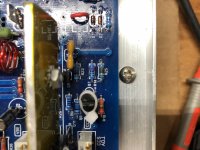
Since this post I have found R25 to be burned and the voltage on speaker outputs has climbed to over 20 volts and I can not adjust it with r17. Even after replacing r25?
Any suggestions on where and what to look at would be greatly appreciated.
Attached Thumbnails
I had posted this on the other thread thought might be better served here!
diyAB Amp - The "Honey Badger"
Hi folks I have read the complete thread here at DYI, a ton of experience and information. Very thankful for all your experience. I have built a few amps in my time, however I am no way any shape an expert at electronics, its a great hobby for me.
I am having issues with the Build I have the new boards 2.4 from the Dyi store bought all the parts from Mouser or DigiKey. I have double check triple checked the placement of the parts, but to no avail I have something messed up and I cant figure what it is.
When I power it up with a bulb tester, the bulb does not glow, the two leds light up. And my voltage on the 10 ohm instead of fuses goes up past 1 volt quickly, the Tp1 and Tp2 millivolts low to zero or negative.
DC offset reading from the Speaker output to ground voltage goes up as I increase the voltage from the variac, and the bulb will light as I increase the variac, but goes out as the caps charge and no adjustment will change it. When and I can start to smell a burning so I turned it off quickly.
I used all the parts from the BOM listed on the Dyi audio store site. The BOM is confusing due to the age of it in relation to the newest Sch dated 12/22/2016, some of the resistors are different there.
PSU is Dyi Audio board 3 with Antek 10445 dual transformer, NTE35 amp rectifiers Dual, All caps are from DigiKey 80v 10,000uf. The PSU checks out fine with the rails being 63v 0v -63v.
I must have a transistor installed incorrect, I have check all these and double check the components. I built both boards at the same time installing the components per location on each board after verifying the part. Both boards do the same thing. The leads me to believe I must have the same misplacement but I can't seam to find it no mater how many times I check it. I did have to use MPSA18 instead of SS-9014 I saw some folks with issues there.
Since this post I have found R25 to be burned and the voltage on speaker outputs has climbed to over 20 volts and I can not adjust it with r17. Even after replacing r25?
Any suggestions on where and what to look at would be greatly appreciated.
Attached Thumbnails
I had posted this on the other thread thought might be better served here!
diyAB Amp - The "Honey Badger"
First check all the leads on the output transistors to ground for continuity. You should have none. If so you have a short to ground. Pictures might help as well. Do you know what component smokes? That is a good clue as well.
Trouble shooting Badger build.
Thank you for the reply, I indeed checked all the output transistors for ground continuity, None detected , I double checked all joints all look well. Check all components all in the correct position and place, all values are correct.
R25 burned I replaced it and it burned again, I have checked the output to ground and I have DC voltage that climbs as I increase the voltage, at the same rate as the input voltage as I increase the variac through the bulb tester.
I am wondering about the decoupling caps and I double checked and there all in correctly, and are from mouser.
I replaced Q1 and Q2 just to check to see if I had a poor match MPSA18, no change DC offset voltage Climb, pulled the 15W zener and replaced it with a resistor to see if I had that was incorrect no change to DC offset still climbs with DC voltage.
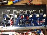
I pulled it from the heat sinks double checked all transistors again all look correct. I am going to pull the caps and replace them to see if I have a bad batch because both boards are doing exactly the same-thing.
I check the PSU and it is right on 63v 0 -63v. I cannot find a short any where on the board. Do I have the Grd connected to the correct point from the PSU to the Board: it is to the star ground on the board no place other than this.
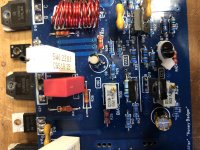
see the attached pictures.
First check all the leads on the output transistors to ground for continuity. You should have none. If so you have a short to ground. Pictures might help as well. Do you know what component smokes? That is a good clue as well.
Thank you for the reply, I indeed checked all the output transistors for ground continuity, None detected , I double checked all joints all look well. Check all components all in the correct position and place, all values are correct.
R25 burned I replaced it and it burned again, I have checked the output to ground and I have DC voltage that climbs as I increase the voltage, at the same rate as the input voltage as I increase the variac through the bulb tester.
I am wondering about the decoupling caps and I double checked and there all in correctly, and are from mouser.
I replaced Q1 and Q2 just to check to see if I had a poor match MPSA18, no change DC offset voltage Climb, pulled the 15W zener and replaced it with a resistor to see if I had that was incorrect no change to DC offset still climbs with DC voltage.
I pulled it from the heat sinks double checked all transistors again all look correct. I am going to pull the caps and replace them to see if I have a bad batch because both boards are doing exactly the same-thing.
I check the PSU and it is right on 63v 0 -63v. I cannot find a short any where on the board. Do I have the Grd connected to the correct point from the PSU to the Board: it is to the star ground on the board no place other than this.
see the attached pictures.
Attachments

Last edited:
If I understand you correctly this is on both channels. If I were you I would unhook the PS from the boards and check to see if the problem is in the power supply section. Most problems I have had and read about involve just one channel and not both.
Reply trouble shooting
Thank you for the reply, Yep did that even used a different power supply with the same result .
On the input v+ I have 63v. V- I have -63 ground I have zero. I used the Nelson pass push 2 rectifying bridges
To verify the ground coming from the power supply is connected to the amp boards on the terminal next to the speaker Gnd is this correct ? I am beginning to think I lost my way. 😕
trouble shooting Badger build.
Yes it is on both boards, I have disconnected both tested the supply then I have another supply I used to check and have the same result.
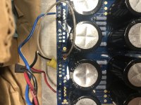
Here is a snap of the connections on the supply. If I understand correctly the GnD from the power supply is connected to the amp board next to the speaker ground. Am i correct?
If I understand you correctly this is on both channels. If I were you I would unhook the PS from the boards and check to see if the problem is in the power supply section. Most problems I have had and read about involve just one channel and not both.
Yes it is on both boards, I have disconnected both tested the supply then I have another supply I used to check and have the same result.
Here is a snap of the connections on the supply. If I understand correctly the GnD from the power supply is connected to the amp board next to the speaker ground. Am i correct?
Attachments

I am fairly certain if you are describing ground as I think that it is correct. Have you tried hooking one board at a time up and see if it is both channels and not just one?
Misterwinefine, check the bias trimer R30.
I think that is 50R.
The 500R trimer should write 501.
I think that is 50R.
The 500R trimer should write 501.
I am fairly certain if you are describing ground as I think that it is correct. Have you tried hooking one board at a time up and see if it is both channels and not just one?
Yes sir I have tried just one board same result. I have double checked the caps all are good took them out to make sure.
The trimmer that adjust dc offset is r17 that can’t be installed in reverse?
One of the issues with this build is there are some conflicting information on the versions that are confusing. On rev 2.4 the bom I ordered was on the day store and has the older parts.
I guess I need to pull all the transistors out and start over? I am stumped on why! I built plent of other dyi builds and had not hit this brick wall. Guess I need to put this down and give it a rest!
And thank you for the help any other ideas would be appreciated!
Misterwinefine, check the bias trimer R30.
I think that is 50R.
The 500R trimer should write 501.
Yes sir it is 500r and according to the schematic it is suppose to be 500 r. I had set it to 500r prior to powering as per the build instructions .
Next I would pull the output transistors and see if you still have a dead short. That way you will know if the problem lies in the pre or output stage.
trouble shooting
I will give that a try and report back tomorrow. Thanks for hanging with me on this one.🙂
I will give that a try and report back tomorrow. Thanks for hanging with me on this one.🙂
Localizing the problem to one circuit is the first thing a repair technician does. Just work with one board and get it to working before hooking up the other board. When you pull the output transistors you can check them with just a multimeter for shorts. Youtube "test transistor with multimeter" to find out how. There is a good chance the problem is going to lie in the power section.
If you are burning up r25 Q9 must be passing way too much current meaning there is either a problem with Q9 or it's base voltage is too low from either Q6 not passing current or Q3 passing too much current.
Pulled the power transistors
I have pulled the power transistors they do not seem to be shorted checked withe MM I will now pul q9 , q6 q3 and check those next, you folks are awesome withe the help thank you. Will report back.
I have pulled the power transistors they do not seem to be shorted checked withe MM I will now pul q9 , q6 q3 and check those next, you folks are awesome withe the help thank you. Will report back.
You have made progress in finding problem then. Fire it up and see if you still have short.
I hope with a dim bulb tester. jwilhelm's advice is a good place to start if you still have short.
I hope with a dim bulb tester. jwilhelm's advice is a good place to start if you still have short.
Troubleshooting
Always use bulb tester saves a lot of parts will report back
You have made progress in finding problem then. Fire it up and see if you still have short.
I hope with a dim bulb tester. jwilhelm's advice is a good place to start if you still have short.
Always use bulb tester saves a lot of parts will report back
Pulled all the transistors and are double checking I ordered new ones from mouser waiting on them all the old ones checked out with a dmm on diode check but I also ordered a dc 45 checker to make sure
It's likely worth putting the transistors back in and checking current flow and voltages to see what's happening. There are some target voltages listed on the schematics. You can measure voltage drops across resistors and calculate current flows to see what's operating too.
- Home
- Amplifiers
- Solid State
- diyAB Amp The "Honey Badger" build thread