the new boards and old BOM/schematic can not be the root of the problem. I've build a 5ch amp last year with the 2.4 boards, and used the BOM from the store. Unliky you, i used SS9014 for Q1,Q2. And VAS/VBE transistors are not the same. Othervise it's all the same. And i hadd no isues with the amp. It has been running for a year now with no problems what so ever. Wel, there is one difference. I don't use the LC cap.
I removed the LC cap as well, like I said before I wasn’t sure what the heck happened but I did remove a lot of parts and remounted then changed those specific parts out and the got it working, I still got to get the other board to work so I will do the same. I could not find the ss9014 ! Your more likely correct, I will see tomorrow if I can get the 2nd board working?
Thank you for encouragement I was getting frustrated with it, onward!
Component values did not create your problem nor changing them solved it. There must have been something wrong with your old component(s) or something wrong with old soldering or something that new soldering fixed (eg invisible hairlike connection or crack or ...).
Look at my HB. It was soldered on v2.3 board with components and values showed with the exception of power transistors. I used MG6331/9411 but in modelling I used njl as MG models are not available.
cheers,
Look at my HB. It was soldered on v2.3 board with components and values showed with the exception of power transistors. I used MG6331/9411 but in modelling I used njl as MG models are not available.
cheers,
Attachments
There was a short somewhere for sure. Strange it was on both boards. Sounds like it had to be something in common. It does sound like a component but then shi** happens.
Making progress
I agree with both of you I suspect it to be a component because on the second board I am slowly removing and checking components and have not found it yet it still is acting like the first board and since I populated the boards together and they both had the same problem it has to be component issue unlikely a solder joint although **** happen s just glad making progress thank you guys!
I agree with both of you I suspect it to be a component because on the second board I am slowly removing and checking components and have not found it yet it still is acting like the first board and since I populated the boards together and they both had the same problem it has to be component issue unlikely a solder joint although **** happen s just glad making progress thank you guys!
I was expecting you would find a wrong value resistor in the CCS area of the input stage.
You know that’s what I thought too, but they all necked out we will see on the other board what I find!
both boards up and running
Want to thank you folks for the help. Got them both up, I think I had one bad component that caused the issue, it was in the input stage and I am not ever sure which one.
I do know this I have a lot of spare parts. Now I am on to the next stage testing the sound and I already have built the box.
When I get it sound tested and in the box I will report back Again thank you all for the help.
You know that’s what I thought too, but they all necked out we will see on the other board what I find!
Want to thank you folks for the help. Got them both up, I think I had one bad component that caused the issue, it was in the input stage and I am not ever sure which one.
I do know this I have a lot of spare parts. Now I am on to the next stage testing the sound and I already have built the box.
When I get it sound tested and in the box I will report back Again thank you all for the help.
Attachments
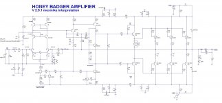
Just made a few changes as noted in the revision box.
Hi stuartmp,
I liked your easier on the eye Honey Badger Sch - V2.5.1 schematic and pushed and pulled my LTspice sim around to agree with it (I shorted some of the caps for FFT analysis following a YouTube video I saw, so not permanent)
Connecting D10 and C7, as per your schematic, to Q9's collector gave some nasty results on the positive peaks of the output with 0.6%THD, which took minutes to simulate.
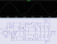
Connecting D10 and C7 to Q9's Base gave really nice results at 1KHz and simulated normally.
Harmonic Frequency Fourier Normalized Phase Normalized
Number [Hz] Component Component [degree] Phase [deg]
1 1.000e+03 4.025e+01 1.000e+00 -0.36° 0.00°
2 2.000e+03 1.124e-05 2.794e-07 122.52° 122.88°
3 3.000e+03 6.243e-06 1.551e-07 26.38° 26.74°
4 4.000e+03 2.804e-06 6.966e-08 118.63° 118.99°
5 5.000e+03 1.063e-06 2.641e-08 1.06° 1.42°
6 6.000e+03 1.296e-06 3.221e-08 119.89° 120.24°
7 7.000e+03 2.006e-07 4.984e-09 4.85° 5.20°
8 8.000e+03 7.658e-07 1.903e-08 116.16° 116.52°
9 9.000e+03 3.333e-07 8.281e-09 167.07° 167.43°
Total Harmonic Distortion: 0.000033%(0.000000%)
Attachments
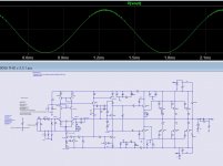
I think its a typo.
The diode and cap go to the base of Q9.
I'm sure Stuart will correct the schematic.
Big thanks to Stuart for doing this.
The diode and cap go to the base of Q9.
I'm sure Stuart will correct the schematic.
Big thanks to Stuart for doing this.
Hi, Guys..
Opps, that was my mistake... sorry...
Lots of things to check when you re arranging things. I missed that..
Thanks Harry. I'll fix it up tonight.
Opps, that was my mistake... sorry...
Lots of things to check when you re arranging things. I missed that..
Thanks Harry. I'll fix it up tonight.
Sounds good what is ideal bias?
What is the ideal bias setting? I am running at 27mv! Ran for 4 hrs today didn’t even get warm
Want to thank you folks for the help. Got them both up, I think I had one bad component that caused the issue, it was in the input stage and I am not ever sure which one.
I do know this I have a lot of spare parts. Now I am on to the next stage testing the sound and I already have built the box.
When I get it sound tested and in the box I will report back Again thank you all for the help.
What is the ideal bias setting? I am running at 27mv! Ran for 4 hrs today didn’t even get warm

Nice, I was trying to figure out if I had done something wrong.
Following stuartmp's v2.5.1 schematic. Needs error checking!
Attachments
Last edited:
What is the ideal bias setting? I am running at 27mv! Ran for 4 hrs today didn’t even get warm
Your fine. As long as you do not see any crossover distortion on your scope your bias is fine. Of course you could raise it more to stay in class A longer if you wish but not really necessary. If you wanted class A you could always build a Firstwatt clone. I left my bias much as yours is now. I have many FW clones if I want to stay in class A.
I have two other questions
You have been extremely helpful, I have two questions.
LC Cap, your experience with it or without it. I have left it out at this point.
How to set up to measure crossover distortion, Where and how to measure it. Did a search for that couldn't come up with the method.
as always I thank you for your experience and help.
Regards.
Your fine. As long as you do not see any crossover distortion on your scope your bias is fine. Of course you could raise it more to stay in class A longer if you wish but not really necessary. If you wanted class A you could always build a Firstwatt clone. I left my bias much as yours is now. I have many FW clones if I want to stay in class A.
You have been extremely helpful, I have two questions.
LC Cap, your experience with it or without it. I have left it out at this point.
How to set up to measure crossover distortion, Where and how to measure it. Did a search for that couldn't come up with the method.
as always I thank you for your experience and help.
Regards.
It has been a while since I built mine but if memory is correct I left the LC cap out.
You will see crossover distortion on your scope if you have any. Inject 1K hz signal into amp and look to see if sine wave is good without a wiggle. As far as measuring such it takes a distortion analyzer or what I use Arta software to measure distortion. With what you have your amplifier biased at you will not have any crossover distortion. Pretty sure that is.
Good Example Of Notch Or Crossover Distortion - YouTube
Feedback does a pretty good job of hiding crossover distortion on a scope. A distortion analyzer or a good sound card and software are better.
those without meters or scopes can adjust bias with music playing at very low volume and then listen for distortion, increasing bias till the sound quality is much improved.....
- Home
- Amplifiers
- Solid State
- diyAB Amp The "Honey Badger" build thread