Updated Schematic - V2.5.2
Thanks for reviewing the schematic Harry.
I have made the changes as noted in the revision box.
Can a forum administrator please delete post #4362 in this thread and
post #2160 in the other HB thread.
I think its a typo.
The diode and cap go to the base of Q9.
I'm sure Stuart will correct the schematic.
Big thanks to Stuart for doing this.
Thanks for reviewing the schematic Harry.
I have made the changes as noted in the revision box.
Can a forum administrator please delete post #4362 in this thread and
post #2160 in the other HB thread.
Attachments
Crossover distortion
All is well with crossover distortion, using scope and generator, It is good on both channels. I don't have a distortion analyzer. But I think all is good so far.
I am thinking of putting in a socket in the LC position to try it out If I do that would I reset bias and offset?
It has been a while since I built mine but if memory is correct I left the LC cap out.
You will see crossover distortion on your scope if you have any. Inject 1K hz signal into amp and look to see if sine wave is good without a wiggle. As far as measuring such it takes a distortion analyzer or what I use Arta software to measure distortion. With what you have your amplifier biased at you will not have any crossover distortion. Pretty sure that is.
Good Example Of Notch Or Crossover Distortion - YouTube
All is well with crossover distortion, using scope and generator, It is good on both channels. I don't have a distortion analyzer. But I think all is good so far.
I am thinking of putting in a socket in the LC position to try it out If I do that would I reset bias and offset?
Thanks for reviewing the schematic Harry.
I have made the changes as noted in the revision box.
Can a forum administrator please delete post #4362 in this thread and
post #2160 in the other HB thread.
Should R19 not be connected to the positive rail and the junction of the zener and the base of Q3 and Q4? Now it only on the zener and bases.
What, wow, That trace just deleted itself... what a joke... sorry guys... if fix it up.Should R19 not be connected to the positive rail and the junction of the zener and the base of Q3 and Q4? Now it only on the zener and bases.
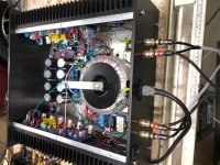
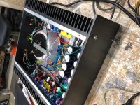
Finished and working great
Wanted to thank all you folks for the help and trouble shooting advice, I have the Honey Badger up and running and it sound awesome. Its in it hand machined box that I did myself, and had that anodized locally.
I have let it run for hours and it doesn't even get warm.
Again thankyou all and a special thanks for working with a novice. You made all the difference.
Learned a lot.
Regards,
Attachments

Updated Schematic - V2.5.3
Updated as required
Should R19 not be connected to the positive rail and the junction of the zener and the base of Q3 and Q4? Now it only on the zener and bases.
Updated as required
Attachments
Man, this build thread is like the largest ball of string... I humbly suggest that it might be time to lock this, keep it for reference, and start another with the latest info.
This amp was supposed to be a first second build kinda deal... I've built many more than that and I'm seriously thinking I should donate my boards and move on.
There are just too many schematics, too many board versions, too many obsolete parts, and ya, 5 or so pages on what to call a ground.
For a FTB, I would tell them to run, not walk from this build.
I don't want to offend, there are many of you who have done much work, but for us solder monkeys, it's very hard to find the banana without starving.
JT
Last edited:
Updated as required
Hi stuartmp
Now the base of Q3 and Q4 are connected to Vcc 😉
Best regards
rephil
Fark... sorry guys, this is what happens when you have to many things going on in your life and you don't get time to focus properly on what you are doing.Hi stuartmp
Now the base of Q3 and Q4 are connected to Vcc 😉
Best regards
rephil
Hi stuartmp
Now the base of Q3 and Q4 are connected to Vcc 😉
Best regards
rephil
Good catch. 😉
Regards.
Man, this build thread is like the largest ball of string... I humbly suggest that it might be time to lock this, keep it for reference, and start another with the latest info.
This amp was supposed to be a first second build kinda deal... I've built many more than that and I'm seriously thinking I should donate my boards and move on.
There are just too many schematics, too many board versions, too many obsolete parts, and ya, 5 or so pages on what to call a ground.
For a FTB, I would tell them to run, not walk from this build.
I don't want to offend, there are many of you who have done much work, but for us solder monkeys, it's very hard to find the banana without starving.
JT
I stuck to the build guide with no problems. That is a good place to start and if willing, try the other advice later. I did not find the parts hard to find at digikey and mouser. The active parts used are the common replacement parts for old amplifiers and receivers. The improvement case is for any older design with diy'ers. The "lets make it better" syndrome. I did learn a lot about bjt designs and build with this amplifier project. I would agree it is probably not for a beginner project. I had fun building it and learning more with some hiccups along the way which other members gladly offered their help solving. Give it a try, do not let the long thread scare you off if you have other builds under your belt. The build guide does work proven by many builds over the years.
Last edited:
I'm with wdecho, this is a good first time build, however I also agree that the thread is a bit of a bear. I made my first amplifier by following the build guide. And then I made another one. And they sound very good.
I do think a consolidated current info thread could be beneficial for first time builders. There is a wiki page, that would seem to me to be the correct place to put agreed upon information. Problem is updating it in an ongoing basis to keep it current. The info is in this thread, but scraping it to get the right info (and who decides it is) is a time consuming and difficult process.
Here is the wiki if you want to check it out.
diyAB Amp, aka. The Honey Badger
Yep the HB is a good project (not only) first time builders. Its may not be as simple as an ACA, but it a very different beast. The build guide is good, no matter if its a few years old. The wiki is useful, too. The thread is good for ongoing discussion and help with specific questions.
The wiki page is in need of an update. SS9014 (Q1 and 2) is realy hard to come by. And they are absolite. I got my hands on 50pc of SS9014c yesterday, from France.
I was lucky and found some MPA18 and found a matched pair on the ones I bought. There is a list of alternatives to use including the readily available 2N4401 that I would not hesitate in using knowing what I know now. The BC**** number I forget is also a good one to use but harder to tie together for thermal tracking. I understand there is a thermal glue one can use. There are many other Q1 and Q2 transistors one could use including probably the KSC1845.
With some homework looking at data sheets you will find transistors that will work at every stage of amplification. Alltransistor.com is a good place to start. For newbies as an example. Bipolar Transistor Cross-reference Search | Equivalent Transistors Homework needed to done on a good substitute. Lots of choices. The options are for the SS9014
NST650xx series is a new smd dual NPN matched transistors.
There are dual PNP matched too.
I wonder why not use them?
There are dual PNP matched too.
I wonder why not use them?
- Home
- Amplifiers
- Solid State
- diyAB Amp The "Honey Badger" build thread