Just an FYI for those who don't match. The 1845s variation I'm seeing in the same tape is nuts. I'm on part 10 and I have an hfe of 340 to 422. :O
Mouser part KSC1845FTACT-ND
JT
Mouser part KSC1845FTACT-ND
JT
Update: I went through 100pc of these and the hfe very up to 60hfe from one part to the next on a strip...
Jt
Jt
Last edited:
Part matching... How far did go,or not go, in matching parts for this build?
So far I have looked at Q1-Q9 and matched them up.
So far I have looked at Q1-Q9 and matched them up.
One of the all advantages of DIY is that one can measure and match components. It does not take much time and almost entirely prevents problems.
cheers,
cheers,
If one does not match critical parts it will work but not to the potential the amplifiers is capable of. The way Q1 and Q2 work together they should be matched as close as possible. With some research on a differential pair or LTP as it is called you will find out why. Much can be said for the cascode and current mirror pairs. Even a rudimentary match of hfe with one of the very cheap Chinese all in one testers is better than nothing at all. Most multimeters can check hfe as well. The hfe will not be precise but again better than no testing at all.
Have the power supply stuff done well as the two soft starts and one speaker protect. Since this is dual mono, do I want/need to use two DC protector to keep the left/right separate for ground issues or anything?
This is the first time I have used the DC protection boards, since it's built for two channels, I didn't build the second...then I got to thinking about it and thought I would get your input.
Merry Christmas!!
JT
This is the first time I have used the DC protection boards, since it's built for two channels, I didn't build the second...then I got to thinking about it and thought I would get your input.
Merry Christmas!!
JT
Pay close attention to the grounding. There can only be one route possible for ground current to flow, otherwise you are susceptible to ground loops. In a dual mono build its usually best to use a separate loop breaker for earth ground for each supply. Pay attention to gronding in the DC detection portion of the speaker protection. They should be separate from each other too.
the speaker ground return wire must be returned to the meeting point of the psu filter caps, as a matter of practice, i do not wire that return wire to any amp pcb ground....
Thanks for the input guys...
In my extensive research for this build I also read Ostripper from here: diyAB Amp The "Honey Badger" build thread
Originally Posted by johngalt47
What is the minimum and maximum gain I should use for the various transistors?
Most of my present 992/1845's are @ 200Hfe. They work in my wolverine-badger
perfect (almost the same circuits).
>400 can be used , the Re's (R15/16 -20/21) could be raised slightly for Q1/2 -5/6 to compensate. BTW - Q5/6 can be low voltage - ksc1815"
This has my attention since my beta are around 400-500.
So if we should increase Re's in such a case, how much should we increase?
JT
jfets have infinite hfe's requiring no gate currents, just voltage fields at their gates...
hfe of 200 is fine, the more important requirement is that they match for hfe and vbe...for a close to zero volts output offset voltage..
hfe of 200 is fine, the more important requirement is that they match for hfe and vbe...for a close to zero volts output offset voltage..
Lost one channel on power up today after 8 weeks no issue
Honey Badger was running really well sounding very good, for over a month , this afternoon I powered it up and I got a pop, opened it up lost the left Chanel , blew one fuse on the v+ side F1 and took out the resistor r53 bias was set at 25 on both channels with no issues prior to this fault!, Need some advice on what to look for and troubleshooting I haven’t replaced the resistor, I am hopping the speaker protection worked I would really be bummed out if I blew my speakers.
Suggestions are greatly appreciated!
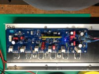
Wanted to thank all you folks for the help and trouble shooting advice, I have the Honey Badger up and running and it sound awesome. Its in it hand machined box that I did myself, and had that anodized locally.
I have let it run for hours and it doesn't even get warm.
Again thankyou all and a special thanks for working with a novice. You made all the difference.
Learned a lot.
Regards,
Honey Badger was running really well sounding very good, for over a month , this afternoon I powered it up and I got a pop, opened it up lost the left Chanel , blew one fuse on the v+ side F1 and took out the resistor r53 bias was set at 25 on both channels with no issues prior to this fault!, Need some advice on what to look for and troubleshooting I haven’t replaced the resistor, I am hopping the speaker protection worked I would really be bummed out if I blew my speakers.
Suggestions are greatly appreciated!
It could be as easy as a faulty fuse.
Was there any smell or burns? Check output devices for shorts.
Also check for chorts between V+ and V- and output and gnd. If there is a short here, also check if D4-D5 is faulty.
Was there any smell or burns? Check output devices for shorts.
Also check for chorts between V+ and V- and output and gnd. If there is a short here, also check if D4-D5 is faulty.
Last edited:
hard to tell with the info given....i will check the output trannies on the b+ side for schorted collector emitter junctions, an open re resistors can be a giveaway..
Last edited:
Checked all the parts suggested.
Ok so I checked for shorts on all power trans none, and checked the Diodes suggested all look good no shorts, replaced the resistor that went up in smoke R53 That did burn.
Checked for shorts from transistor's to heat sink all good there.
replaced the fuses with 10 ohm resistors, checked the power going in on both rails looks good at 58+ 0 58- on current limited bulb tester, powered the one board back up. I got voltage going into the v- side, and v+ side, the led on the Negative side lights up the positive LEDD6 does NOT light up, check to make sure it was ok and it is.
I have + v on the R 32 on the input power rail side, nothing going out on the other side of the resistor. R32 calls for a 22r value in circuit I get running value, I will have to pull it to measure it. The caps look ok,
Q5 and Q6 Q3 and Q4 Need to be pulled to see if they are OK? Or do i need to look else where??
Thanks for the help folks.
hard to tell with the info given....i will check the output trannies on the b+ side for schorted collector emitter junctions, an open re resistors can be a giveaway..
Ok so I checked for shorts on all power trans none, and checked the Diodes suggested all look good no shorts, replaced the resistor that went up in smoke R53 That did burn.
Checked for shorts from transistor's to heat sink all good there.
replaced the fuses with 10 ohm resistors, checked the power going in on both rails looks good at 58+ 0 58- on current limited bulb tester, powered the one board back up. I got voltage going into the v- side, and v+ side, the led on the Negative side lights up the positive LEDD6 does NOT light up, check to make sure it was ok and it is.
I have + v on the R 32 on the input power rail side, nothing going out on the other side of the resistor. R32 calls for a 22r value in circuit I get running value, I will have to pull it to measure it. The caps look ok,
Q5 and Q6 Q3 and Q4 Need to be pulled to see if they are OK? Or do i need to look else where??
Thanks for the help folks.
Attachments
Update On trouble
Ok I replaced the R32 it measured open out of circuit repowered the board and I have the + Led back ,
So the question what would have caused this to fail is there something up stream or down stream I need to look at?
I haven't done a full power up just yet looking for other suspects.
Again thank you folks.
- Home
- Amplifiers
- Solid State
- diyAB Amp The "Honey Badger" build thread