yes, but not much...
Tru dat. I guess the main function is to make it easy to determine the setting of the constant current source pot.
tommost
What's the Vce rating of Q7? Maybe this resistor helps to cope with the actual voltage.
Best regards!
Best regards!
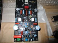
To Honey Badger experts, What is the purpose of R14 in the amplifier? See attachment.
I have seen it in other amps, but I don't get what does it do.
Thanks!
Perhaps to decouple the differential pair from the neg rail at high frequency better? Its in series with Q7's base-collector capacitance.
Hi Tom,
Yes, that is about the only thing it does at 2K2. It could also isolate any capacitance between the CCS and the circuit in case you had a heat sink on the transistor.
-Chris
Yes, that is about the only thing it does at 2K2. It could also isolate any capacitance between the CCS and the circuit in case you had a heat sink on the transistor.
-Chris
the small ccs is touching the heatsink and is quite some distance away from the input ltp, so that is also a probable reason, decouple stray capacitance and add stability...
What's the Vce rating of Q7? Maybe this resistor helps to cope with the actual voltage.
Best regards!
more than enough it seems.....at Vceo of 120, https://www.mouser.ph/datasheet/2/308/KSC1845-1295526.pdf
the small ccs is touching the heatsink and is quite some distance away from the input ltp, so that is also a probable reason, decouple stray capacitance and add stability...
Hi Tony, why does the heatsink matter regarding R14? I did not follow. Also what heatsink is being referred to here, the OPS heatsink?
Regarding the CCS stray capacitance, it does not matter much for stability. In a diff-pair (or LTP) the node where the current source feeds the pair is small signal ground for differential mode.
In common mode, the cap does play a part resulting in 2nd order distortion at higher frequencies, but usually well beyond the audio range.
Finally, let's think numbers. If the stray cap at the node was 10p, the time constant with 2.2k would be 7.24MHz, to high to matter. Even if was 30p, that would still be 2.4MHz.
Last edited:
Hi Tony, why does the heatsink matter regarding R14? I did not follow. Also what heatsink is being referred to here, the OPS heatsink?
if you built this amp, there is a small heatsink where the VAS, the big CCS, small ccs are mounted, this is the heatsink i was reffering to, not the big heatsinks where the power output devices are mounted..
Regarding the CCS stray capacitance, it does not matter much for stability. In a diff-pair (or LTP) the node where the current source feeds the pair is small signal ground for differential mode.
In common mode, the cap does play a part resulting in 2nd order distortion at higher frequencies, but usually well beyond the audio range.
Finally, let's think numbers. If the stray cap at the node was 10p, the time constant with 2.2k would be 7.24MHz, to high to matter. Even if was 30p, that would still be 2.4MHz.
you do not have to convince me, not my idea anyway, i just gave a plausible reason....instabilities in the mhz region can happen more than we know...
that is why the base stoppers...strays in the 30pf are not uncommon...
if you built this amp, there is a small heatsink where the VAS, the big CCS, small ccs are mounted, this is the heatsink i was reffering to, not the big heatsinks where the power output devices are mounted..
Got it... I have not built it, so I did not know the CCS had its own heaksink.
HoneyBadger Oscillating Under Load
I built two honeybadgers same components as in the schematic just some of the transistors are higher hfe grade, it would oscillate at 400KHz on the top of the waveform if I played a sign wave at 50 watts or higher this was into a 8 ohm subwoofer, I Got it to stop by putting two 220pF caps across the two 47pF's next to the driver transistors I also removed the LC cap and C6 as suggested in the forum it has less ringing after removing those parts, I would like to make sure my modifications are okay and not ruining the transient response or some other unknown thanks for the help.
I built two honeybadgers same components as in the schematic just some of the transistors are higher hfe grade, it would oscillate at 400KHz on the top of the waveform if I played a sign wave at 50 watts or higher this was into a 8 ohm subwoofer, I Got it to stop by putting two 220pF caps across the two 47pF's next to the driver transistors I also removed the LC cap and C6 as suggested in the forum it has less ringing after removing those parts, I would like to make sure my modifications are okay and not ruining the transient response or some other unknown thanks for the help.
I built two honeybadgers same components as in the schematic just some of the transistors are higher hfe grade, it would oscillate at 400KHz on the top of the waveform if I played a sign wave at 50 watts or higher this was into a 8 ohm subwoofer, I Got it to stop by putting two 220pF caps across the two 47pF's next to the driver transistors I also removed the LC cap and C6 as suggested in the forum it has less ringing after removing those parts, I would like to make sure my modifications are okay and not ruining the transient response or some other unknown thanks for the help.
can you have it marked as your as built drwing for the benefit of others.....i guess for subwoofer duties, you need not have such a wide bandwidth...
what was your turn over frequency for your sub?
I will draw on the schematic when I get on my desktop, I'm gonna use it for full range use a did a sweep from 20Hz-15KHz and didn't see any decrease in amplitude how much does doing that decrease the bandwidth ?
Got it... I have not built it, so I did not know the CCS had its own heaksink.
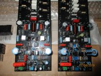
this is a modern day design and really delivered the goods....
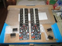
i built a multi pair version with SOA limiting circuit...
Attachments
I will draw on the schematic when I get on my desktop, I'm gonna use it for full range use a did a sweep from and didn't see any decrease in amplitude how much does doing that decrease the bandwidth ?
is that full power bandwidth of 1 watt level bandwidth?
20Hz-15KHz is an excellent number....
this is a modern day design and really delivered the goods....
i built a multi pair version with SOA limiting circuit...
Hi Tony, while I have not built the HB, I am well acquainted with the design and spent quite some time with it on LTSpice. Ozz was kind enough to provide a .asc for me to use. I guess the .asc does not say where heatsinks are.
Actually, I am using the HB as the baseline for my current project, the SW-VFA-01. As part of the of the design, I started an educational Youtube video channel where I share my knowledge on audio amplifier circuit design. The structure of the videos kinda follow the Cordell and Self books, but they have my own spin to things.
You can find the channel here:
SWAudio
The link is also on my signature below.
Thanks for all the info,
SandroHV
Pretty far I'm thinking about half power if not less the clipping was really distorted until I added those caps, now it clips normally
- Home
- Amplifiers
- Solid State
- diyAB Amp The "Honey Badger" build thread