RN60 resistor can not be used. most of the 0.6W resistors have too thick leads. max lead diameter is 0.55mm exept 1-5W resistors.
I have another question to those who built the amp: where you able to use electrolytics of bigger diameter and lead spacing than the ones stated in the BOM, and vishay dale rn60 resistors?
Cant't use rn60, I use rn55 and there are 0.6w that can fit, for example vishay mrs25 , te lr1 series. You can buy from mouser rs etc. For electrolytic, I user the one that fit pcb, panasonic fc are small enough.
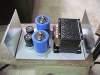
this is my completed HB amp..
Attachments


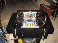
this is my completed HB amp..
Cool build Tony!
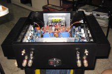
Are the knobs on the aft panel for source selection?
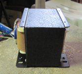
What did you use for rectifiers( I think that's what I see on top of the xfmr)?
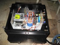
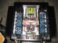
Tony, looking good !! 🙂 I like the clamping method that you use to fasten the transistors, much easier then have to drill a hole for each transistor.
Last edited:
this is my completed HB amp..
Very clean construction! What value are the filter capacitors?
Cant't use rn60, I use rn55 and there are 0.6w that can fit, for example vishay mrs25 , te lr1 series. You can buy from mouser rs etc. For electrolytic, I user the one that fit pcb, panasonic fc are small enough.
You used rn55s for 1/4w resistors? But they are rated for 1/8w. And for 1/2w you used mrs25s? What did you use for 1w?
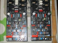
Very fine! What do those smaller electrolytics do?this is my completed HB amp..
Best regards!
Very fine! What do those smaller electrolytics do?
Best regards!
it is supposed to help in the ESR department.
You used rn55s for 1/4w resistors? But they are rated for 1/8w. And for 1/2w you used mrs25s? What did you use for 1w?
carbon film resistors were used....i have tons of them in stock...china stuff mostly..
Very clean construction! What value are the filter capacitors?
big cap is 56000ufd/63vdc; small cap is 10000ufd/63vdc..
Cool build Tony!
Are the knobs on the aft panel for source selection?
What did you use for rectifiers( I think that's what I see on top of the xfmr)?
the pots control volume level so i can connect the cd player directly..
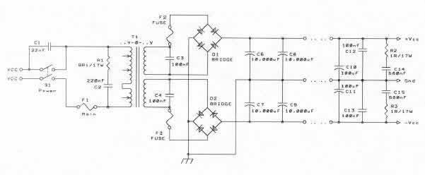
i used inline sanken 50A 1000 volt rectifiers, i did not use a center tap that is why two rectifiers were used..
something like this:
Tony, looking good !! 🙂 I like the clamping method that you use to fasten the transistors, much easier then have to drill a hole for each transistor.
my consideration was ease of servicing....as you can take out the board easily in case you want to replace parts...
Tony,
I used pre-packaged bridge rectifiers as well, mine are in a different package though.
Did you use anything between the "mounting bar" and the transistors to help disperse torque? I'm curious because I was going to do something similar to this idea. I'm still undecided on that for now.
Cheers,
Tim
I used pre-packaged bridge rectifiers as well, mine are in a different package though.
my consideration was ease of servicing...
Did you use anything between the "mounting bar" and the transistors to help disperse torque? I'm curious because I was going to do something similar to this idea. I'm still undecided on that for now.
Cheers,
Tim
Tony,
I used pre-packaged bridge rectifiers as well, mine are in a different package though.
Did you use anything between the "mounting bar" and the transistors to help disperse torque? I'm curious because I was going to do something similar to this idea. I'm still undecided on that for now.
Cheers,
Tim
as you can see i used an angle bar 10mm x 10mm x 2.5 mm so that torque should be evenly dispersed,
my main beef with this HB is the absence of the SOA protection circuit, fuses can not protect your amp so extreme care should be observed using this amp..
i mean SOA protection on the board itself....if i were to come up with a board revision, i will include a soa protection circuit...
Built in protection would be nice, especially for first time builders like myself.
This aside, I guess with all the different variants of badger's out there it would be hard to make a "one size fits all" protection without increasing the footprint significantly.
I plan on going the 21st century route myself, it's quite interesting/advanced set-up. I was reading the thread a year or two back, and it is a very impressive protection system.
but otherwise, this amp is very good sounding, make no mistake about it...
so much so that we came up with our own layout, a TEF version using 9 pairs of output trannies...
so much so that we came up with our own layout, a TEF version using 9 pairs of output trannies...
Attachments
Last edited:
- Home
- Amplifiers
- Solid State
- diyAB Amp The "Honey Badger" build thread