Measure the power supply voltage at each board, from the V+ (hot) to ground.
Watch the probes, and don't slip or short anything.
Watch the probes, and don't slip or short anything.
Last edited:
^ Yes, this is a component specifically meant for tuning the sound of the FE to match one's needs/preferences.
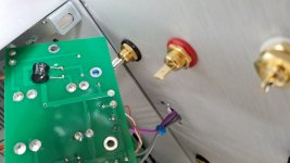
Measure the power supply voltage at each board, from the V+ (hot) to ground.
Watch the probes, and don't slip or short anything.
I measured both boards and I am getting 33.6v on both. I checked the wiring and everything looks like the diagram, but the diagram has the order of the ground inputs on the vfet board in a different order than what's on the board. The only thing I didn't do was something for "Switch 2" because I am not sure what's it for?
Last edited:
There is a lot of discussion in this thread about the SPST switch provided, and substituting a DPST. Or not.
So, have you put a link across SW2?
Yes, you can just short where the 2nd pole goes and use it - it will just have a larger turn-off thump, but not a turn-on thump. This was simply the simplest approach.
So, have you put a link across SW2?
There is a lot of discussion in this thread about the SPST switch provided, and substituting a DPST. Or not.
So, have you put a link across SW2?
No, I haven't put a link. I read last night the part of the thread that has to do with the switch. I just used the switch that came with the kit, while leaving "Switch 2" blank.
I measured both boards and I am getting 33.6v on both. I checked the wiring and everything looks like the diagram, but the diagram has the order of the ground inputs on the vfet board in a different order than what's on the board. The only thing I didn't do was something for "Switch 2" because I am not sure what's it for?
Could this be my problem with the voltage adjustment issue that I initially posted about or is it mainly a turn-on thump suppression?
I am going to triple-check the wiring this morning and see if there are any discrepancies with it.
Looking at the schematic, no connection on SW2 will leave the relay coil un-powered (I think) keeping the speaker output shorted. You could jumper SW2 or disconnect O+ going to the power supply board. Careful to insulate them as they are the main output of the amp.
Some one please correct me if I am mistaken about this.
Some one please correct me if I am mistaken about this.
Finally finished 128 today and listening to sweet sweet music now. 😀
Thanks a lot again everyone involved!
I built it with DPST and the turn on thumb is quite small. At turn-off it's quite a bit more prominent, but not enough that I'd feel uncomfortable (96db speakers).
Thanks a lot again everyone involved!
I built it with DPST and the turn on thumb is quite small. At turn-off it's quite a bit more prominent, but not enough that I'd feel uncomfortable (96db speakers).
I'm getting the same reading of 1.3 at the anode where it was instructed to measure in the build guide. Adjusting the pot does not do anything. I will ask the obviously stupid question: where should I be measuring in order to achieve proper bias?
Last edited:
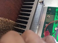
For the N-Channel Sony VFET amps, the bias voltage should be measured between the IRF250 and ground. I clipped leads to the screw head on the IRF250 and the ground wire on the output stage board.
From the Nelson Pass PDF:
"Also, P1 wants to be adjusted to give +14 volts at the Drain (case) of the IRF250, and trimmed after it warms up."
From the Nelson Pass PDF:
"Also, P1 wants to be adjusted to give +14 volts at the Drain (case) of the IRF250, and trimmed after it warms up."
I measured both boards and I am getting 33.6v on both. I checked the wiring and everything looks like the diagram, but the diagram has the order of the ground inputs on the vfet board in a different order than what's on the board. The only thing I didn't do was something for "Switch 2" because I am not sure what's it for?
For the N-Channel Sony VFET amps, the bias voltage should be measured between the IRF250 and ground. I clipped leads to the screw head on the IRF250 and the ground wire on the output stage board.
From the Nelson Pass PDF:
"Also, P1 wants to be adjusted to give +14 volts at the Drain (case) of the IRF250, and trimmed after it warms up."
I checked from the IRF250 and ground, but I'm still getting 1.3? I've attached photos:
Attachments
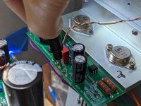
I checked from the IRF250 and ground, but I'm still getting 1.3? I've attached photos:
Measure from ground to the screw circled in this image.
Attachments

- Home
- Amplifiers
- Pass Labs
- DIY Sony VFET pt 2 (N-Channel Build)