What are the differences in systems that account for the variation in turn on and off thumps and pops?
What are the differences in systems that account for the variation in turn on and off thumps and pops?
Good question. Mine is not having any thumps or pops during power on or power off. My speakers sensitivity are around 94db. My amplifier had all stock parts except interconnect wires and the main power toggle switch; I use a DPDT from Mouser Electronics.
speakers db...on my 93db FR turn off thump is quite loud need to mod the relay activation as Pa write .What are the differences in systems that account for the variation in turn on and off thumps and pops?
on two way 86db zero problem
My speakers are ~95 @8ohm. They always show off power on/off thumps when present. My Aleph J amp is a bit scary actually (my highest watt amp) some of the cards for my M2x monos cause some mild noises. (Aleph J is going to evolve to SissySIT R3, with PSU improvements)
If I get lucky to get in on the 3rd round of these amps (I have N and P VFets!) I’ll be looking for the best thump suppression power board.
If I get lucky to get in on the 3rd round of these amps (I have N and P VFets!) I’ll be looking for the best thump suppression power board.
Good question. Mine is not having any thumps or pops during power on or power off. My speakers sensitivity are around 94db. My amplifier had all stock parts except interconnect wires and the main power toggle switch; I use a DPDT from Mouser Electronics.
What switch did you use? Was it DPDT? How did you wire the 6 tabs on the switch? I used Mouser 629-GRS402104. that was mentioned in post 27-29. Switch is DPST. Do you actually get a delay before music plays indicating the relay is actually functioning?
If Mark would be so generous to add an anti-vandal switch to the Theseus ala H9KPXG I think we would have the “Holy Grail” of SMPS management in the future. Although I wouldn’t sully this amp with front panel switch.
Hi Jcon2,
I meant to write DPST. I’m using Mouser 629-GRS-4021-0032. For some reason ai don’t get any annoying stumps when powering up or down. If there is a delay at power up, is not very long.
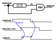
One simplistic design concept that mutes immediately at power-off, but does not un-mute until 20 seconds after power-on, is diagrammed below. It's a conceptual logic network (not a real circuit), whose timing diagram is beneath.
PWRGOOD is high when the +36V power rails within the amplifier, are at +36V. At all other times, PWRGOOD is low.
The PWRGOOD signal is sent through a 20 second delay line, whose (delayed) output is labeled XX.
PWRGOOD and XX are applied to a digital logic AND gate, which tells the muting relay to stop muting the speaker outputs. The AND gate creates a digital signal named UNMUTE.
At power-on, PWRGOOD goes high but XX remains low. Thus UNMUTE = AND(1,0) remains low. 20 seconds later, XX goes high. At that point UNMUTE = AND(1,1) and it goes high. The muting relay is engaged, the speaker terminals are no longer shorted to ground, and the amp starts playing music.
At power-off, PWRGOOD goes low but XX remains high. Thus UNMUTE = AND(0,1) and it goes low. The muting relay is released, the speaker terminals are shorted to ground, and the amp stops playing music.
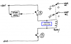
A conceptual implementation is shown in figure 2. In this figure, the logical AND function is implemented by connecting two switches in series with the relay coil. The relay coil is engaged only if switch_A is closed AND switch_B is closed. {practical implementations are quite a bit messier than this drawing; what's shown here is only the basic idea, not the grubby reality}
_
PWRGOOD is high when the +36V power rails within the amplifier, are at +36V. At all other times, PWRGOOD is low.
The PWRGOOD signal is sent through a 20 second delay line, whose (delayed) output is labeled XX.
PWRGOOD and XX are applied to a digital logic AND gate, which tells the muting relay to stop muting the speaker outputs. The AND gate creates a digital signal named UNMUTE.
At power-on, PWRGOOD goes high but XX remains low. Thus UNMUTE = AND(1,0) remains low. 20 seconds later, XX goes high. At that point UNMUTE = AND(1,1) and it goes high. The muting relay is engaged, the speaker terminals are no longer shorted to ground, and the amp starts playing music.
At power-off, PWRGOOD goes low but XX remains high. Thus UNMUTE = AND(0,1) and it goes low. The muting relay is released, the speaker terminals are shorted to ground, and the amp stops playing music.
A conceptual implementation is shown in figure 2. In this figure, the logical AND function is implemented by connecting two switches in series with the relay coil. The relay coil is engaged only if switch_A is closed AND switch_B is closed. {practical implementations are quite a bit messier than this drawing; what's shown here is only the basic idea, not the grubby reality}
_
Attachments
If I get lucky to get in on the 3rd round of these amps (I have N and P VFets!) I’ll be looking for the best thump suppression power board.
If you have the vfets luck will have nothing to do with it.


Bypassing C1 in output stage (output coupling cap)
Just wanted to talk about my experience with bypassing the output coupling cap on the VFET board, the big 10mF Rubycon, C1.
My initial listening impressions with just the standard 0.33uF WIMA MKP2 bypass cap have been here:
https://www.diyaudio.com/forums/pas...y-vfet-pt-2-channel-build-14.html#post6752665
After a few days, that impression still stood. However, I wanted to try bypassing C1, and when the Nichicon Muse ukz 1000uF 50V arrived, I soldered those below board to bypass C1. With 8R loudspeaker impedance, the -3dB frequency for the Nichicons alone would be 20Hz, so already active in the bass and no phase shift to contend with from 200Hz on.
Soo ... the first listening impressions were not very impressive. No real improvement, in fact I thought the music to be less engaging, and less transparent, slightly fuzzy even, compared to just the Rubycon. I thought that maybe two dissimilar caps operating in parallel could be blurring the impulse response because of differing ESR, resp. impedance.
So I was ready to take the Nichicon Muse ukz out again, but then also hoped that giving it some more time might change things, and couldn't make time for soldering either ...
And after about 5 days, the sound really did improve and started to become focused again, and after about a week, it seemed fully developed.
Clarity and 3D I think are even better than before, and my engagement with the music is there again.
The VFET N has developed to the point that even my F4, which I switched in for an evening, sounds a bit fuzzy in comparison, and that did surprise me ... 🙂
One more thing: I have the impression that the VFET N needs to be played a bit louder to fully develop its sound and bring the same engagement that I remember from my SissySIT at lower volumes already.
SissySIT is currently out of commission, in the chassis is the F4, the boards are pillaged to use parts for the SissySIT R.3.
Those boards are actually ready; just need to do some distortion measurements on the F4 before I dismantle that one and put the R.3 boards into that chassis. When the R.3 works, I can compare again ... 😀
Regards, Claas
Attachments
Last edited:
Just wanted to talk about my experience with bypassing the output coupling cap on the VFET board, the big 10mF Rubycon, C1.
[snip]
Soo ... the first listening impressions were not very impressive. No real improvement, in fact I thought the music to be less engaging, and less transparent, slightly fuzzy even, compared to just the Rubycon. I thought that maybe two dissimilar caps operating in parallel could be blurring the impulse response because of differing ESR, resp. impedance.
So I was ready to take the Nichicon Muse ukz out again, but then also hoped that giving it some more time might change things, and couldn't make time for soldering either ...
And after about 5 days, the sound really did improve and started to become focused again, and after about a week, it seemed fully developed.
Clarity and 3D I think are even better than before, and my engagement with the music is there again.
[snip]
I appreciate your going through all of the effort to test your theory and post your impressions. It seems like an awful lot of work to go through, just to end up about where the original design started out. I think I'll just enjoy it as it is! 🙂
Switch on/off thump
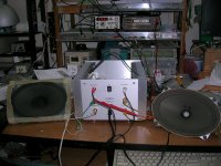
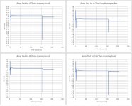
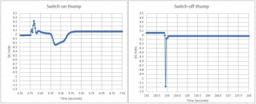
This is what I measured on my build.
First and second attachments are through a soundcard (M-Audio Audiophile USB) 48kHz/24 bit
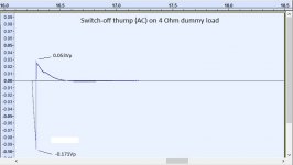
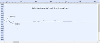
Third and forth are through a DC data acquisition module (DATAQ DI-148U) 240 samples/sec
When close listening with sensitive Isophon speakers (~ 94db sensitivity), switch on thump was barely detectable. Switch-off thump was noticeable but benign.
I don’t see a problem there.
George
This is what I measured on my build.
First and second attachments are through a soundcard (M-Audio Audiophile USB) 48kHz/24 bit
Third and forth are through a DC data acquisition module (DATAQ DI-148U) 240 samples/sec
When close listening with sensitive Isophon speakers (~ 94db sensitivity), switch on thump was barely detectable. Switch-off thump was noticeable but benign.
I don’t see a problem there.
George
Attachments
Yes quite a few Nchannel VFET builders are perfectly happy with their amp as-is, and report either no thumps at all, or acceptably small thumps. But there are a few unlucky people who report big thumps that they find highly objectionable.
Here's a little thought experiment: what would be the effect upon the switch-off thump, if DIY Danielle's capacitor C7 happens to be 11.5 microfarads (15% above nominal) instead of 10 microfarads? Would her thump get louder? softer? unchanged?
(Everyone who hears thumps, reports that the switch-off thump is louder than the switch-on thump; which seems to match the voltage waveforms shown in post #551)
_
Attachments
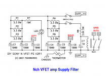
ZMedited Nch_VFET_supply_filter
oh boy
am I wrong, having an impression that suddenly obtaining DPDT switch is greater problem than >winning a Lottery, paying for Ultrarare Goods and actually building it < ......
anyway, nothing wrong with the kiss, boy ......

switch name - I'm always confused with throw and position , so take DPDT just conditionally ........ two sections, simple ON-OFF - that coincides with my logic
oh boy
am I wrong, having an impression that suddenly obtaining DPDT switch is greater problem than >winning a Lottery, paying for Ultrarare Goods and actually building it < ......
anyway, nothing wrong with the kiss, boy ......
switch name - I'm always confused with throw and position
, so take DPDT just conditionally ........ two sections, simple ON-OFF - that coincides with my logicAttachments

Last edited:
Actually, I thought of that ... but in the form factor that fits in the cutout of the VFET chassis, I did only find DPST switches of adequate DC current rating.
The DPDT switches I found did not have a DC current rating I had been comfortable with.
So, I'm leaving it as it is with the DPST ... my turn-off thump is there but not too bothersome 😛
The DPDT switches I found did not have a DC current rating I had been comfortable with.
So, I'm leaving it as it is with the DPST ... my turn-off thump is there but not too bothersome 😛
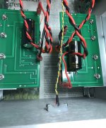
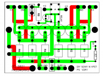
ZenMod, here's the existing PCB layout of the Nchannel VFET supply filter board that builders received. Maybe you can show the locations where your modifications in post #553 need to be made?
Perhaps such as: cut copper trace at location1, scrape away soldermask at location2, solder switch wires to location3 and location4, recommendations like those.
_
Perhaps such as: cut copper trace at location1, scrape away soldermask at location2, solder switch wires to location3 and location4, recommendations like those.
_
Attachments
It would have been nice with a definitive answer if it is worth it. We won't know if it is your ears that got used to it, or if there was an actual improvement other than regular warmup. I find that the P-channel amp changes for every minute after startup.
I used Nichicon KW series 470 uF caps in parallel with the Rubycon output caps in my P type amp. Had similar results to those reported by chede, though I might have noticed some improvement in sound a little earlier. Things definitely improved over more time and I’m happy with the mod.
Last edited:
You live the wima in place too ??Just wanted to talk about my experience with bypassing the output coupling cap on the VFET board, the big 10mF Rubycon, C1.
- Home
- Amplifiers
- Pass Labs
- DIY Sony VFET pt 2 (N-Channel Build)