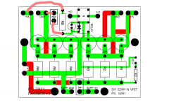
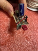
ZenMod, here's the existing PCB layout of the Nchannel VFET supply filter board that builders received. Maybe you can show the locations where your modifications in post #553 need to be made?
Perhaps such as: cut copper trace at location1, scrape away soldermask at location2, solder switch wires to location3 and location4, recommendations like those.
_
I can't, if Boyz are not having definitive solution for obtaining adequate dual section, simple ON-OFF switch
in case of Boyz having definitive consensus regarding switch, I'll be more than happy to make short and sweet tutorial
You leave the wima in place too ??
Yep, Wima MKP2 0.33uF is still there.
Wima MKP are my favourite bypass caps anyway. I try to go for MKP10, but if I have space constraints, am using MKP4 or MKP2 as well.
I never had been happy with the Polyester Wima MKS sound-wise whenever I tried them.
Zen Mod's favourite Philips MKC (there are NOS Wima MKC floating around as well) are very nice as well.
😀
Number 131 is up and running. I managed to build it in record time, at least by my own standards. I left out the front and and am running it currently directly connected to my Yamaha streaming DAC as a power buffer. My loudspeakers are Avantgarde Acoustics DUOs with 104 dB sensitivity, which is why I usually have way too much gain in my system.
What I can say so far is that the amp sounds great, a little brighter than my ZEN V4 but without sounding harsh; the ZEN V4 in turn has more bass slam. The Sony may possibly have a little more resolution than my V4, but the differences overall are relatively small. Voices sound particularly captivating, maybe more so than with the ZEN, but again I am not sure yet.
What I can say so far is that the amp sounds great, a little brighter than my ZEN V4 but without sounding harsh; the ZEN V4 in turn has more bass slam. The Sony may possibly have a little more resolution than my V4, but the differences overall are relatively small. Voices sound particularly captivating, maybe more so than with the ZEN, but again I am not sure yet.
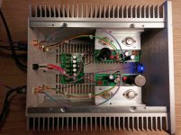
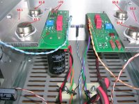

I noted that caps on filter psu are heating a lot ,maybe some hole under resistor is a good thing ,but I put a paper as shielding and work quite good....just try
Hallo Martin,
how much hum can you hear on your Avantgardes ?
With my 100 dB/W Jericho Horns (Fostex 208 Sigma), I can hear a tiny bit of hum up to 20-30 cm away. My room is unusually quiet, however.
Regards, Claas
how much hum can you hear on your Avantgardes ?
With my 100 dB/W Jericho Horns (Fostex 208 Sigma), I can hear a tiny bit of hum up to 20-30 cm away. My room is unusually quiet, however.
Regards, Claas
Hello Claas,
Remember that I do not have the front end, I can only turn the volume of my DAC up to 0 dB (and off course no music playing 😀 ), which would be about 10 dB above my usual listening level.
Then I cannot hear any hiss or hum whatsoever in the left channel, in the right channel and with the ears on the sub-woofer I can hear some very faint hum overtones or rectifier hash, but after unplugging the cables this is still there, so looks like the plate amp is producing this noise.
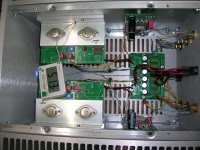
P.S.: I tried to minimise loop areas of the cables by placing each pair of leads as close together to each other as possible, keep the power supply, input and output cables as far away from each other as practical, and the input cables are star quad cables (taken from Sommer microphone cables and without the shield as that does not protect from magnetic poickup anyway). Also, I have no transformer that can pick up hum.
Nelson, thank you for your altruism and generosity. Jason and Elena thank you for such a good job with the store and bulletin board. VFet the most exciting thing in 2021!
I've been building 172 but have hit a problem. Completed the build with care as per guide and Nelson's notes. Got a DPST switch in no problems. Checked wiring 3x. Powered up and tweaked bias to 14v and adjusted after warm up no problems. Heatsink and bracket temperatures felt right. Wonderful Eva Cassidy. Then from L channel fizzing sound and L channel goes quiet, just quiet distorted sound, other channel fine. Bias has changed to 17v possible to rebias to 14v though. Has the worst thing in the world happened and the VFet has died? Also no longer heat generated from L channel. Checked and rechecked wiring all seems good. Gentle advice would be very welcome.
Neil M
Reply to MRupp #571:
Hello Martin,
thanks for the additional info! I suspect the Edcor as playing a key role in the slight hum I have.
As you do, I also tightly twist all wire runs that belong together, and make sure that no power wires run parallel to signal wires.
I have approx. 300-400 uV of AC on the outputs with nothing connected to the amp. If it would bother me, I would probably experiment around the multiple grounding points around the front-end boards / PSU filter area. But as it stands now, I would just leave it as is and be happy 🙂
As another data point, it did take a lot of effort to get my M2 (that also has the Edcors) quiet, whereas my SissySIT with Cinemags did not exhibit any hum.
Best regards, Claas
P-channel, 98dB/w/m speakers, absolutely no hum even with ears on the LS.
Another amp, Class D, famous for being "dead quiet" is indeed so at an inch, but if really "looking" for the faintest noise with ears on the baffle... is "noisier".
I hope this helps
Claude
Another amp, Class D, famous for being "dead quiet" is indeed so at an inch, but if really "looking" for the faintest noise with ears on the baffle... is "noisier".
I hope this helps
Claude
Hello Claas,
If it is really induced hum, it has to come from somewhere. The Firstwatt M2 has higher hum specs than the other amps, but unless I am mistaken it has the power transformer inside the chassis. In your case (no pun intended) there is no internal hum source, so nearby devices or power cords would be inducing the hum. Maybe moving the amp away from all other devices would show a positive result, if only as a test.
The other option would be shielding, Cinemags transformers seem to have a mu-metal shield, that should be there for a reason.
Nelson, thank you for your altruism and generosity. Jason and Elena thank you for such a good job with the store and bulletin board. VFet the most exciting thing in 2021!
I've been building 172 but have hit a problem. Completed the build with care as per guide and Nelson's notes. Got a DPST switch in no problems. Checked wiring 3x. Powered up and tweaked bias to 14v and adjusted after warm up no problems. Heatsink and bracket temperatures felt right. Wonderful Eva Cassidy. Then from L channel fizzing sound and L channel goes quiet, just quiet distorted sound, other channel fine. Bias has changed to 17v possible to rebias to 14v though. Has the worst thing in the world happened and the VFet has died? Also no longer heat generated from L channel. Checked and rechecked wiring all seems good. Gentle advice would be very welcome.
Neil M
The V-fet can be checked with multimeter along with other transistors. Details on how are on youtube and other sources on net. I doubt the problem is the V-fet. They have a reputation of being pretty tough. Google
Nelson, thank you for your altruism and generosity. Jason and Elena thank you for such a good job with the store and bulletin board. VFet the most exciting thing in 2021!
I've been building 172 but have hit a problem. Completed the build with care as per guide and Nelson's notes. Got a DPST switch in no problems. Checked wiring 3x. Powered up and tweaked bias to 14v and adjusted after warm up no problems. Heatsink and bracket temperatures felt right. Wonderful Eva Cassidy. Then from L channel fizzing sound and L channel goes quiet, just quiet distorted sound, other channel fine. Bias has changed to 17v possible to rebias to 14v though. Has the worst thing in the world happened and the VFet has died? Also no longer heat generated from L channel. Checked and rechecked wiring all seems good. Gentle advice would be very welcome.
Neil M
Neil
don't panic!
Systematically check
- V+ on the left channel output board
- Ground on the left channel output board
- shortage on the output?
It could also be helpful, when you post some pictures.
Franz
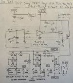
My take on the turn-on/off anti-thump circuit:
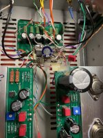
The turn-on thump for me is acceptable and I hear no turn-off thump, but I decided to redo that circuit anyway. Now there is a kludge glued tenuously to one OS board and its own wires. Maybe I should have at least put some blue LEDs on it!
But here it is, which separates the relay from the RC. I wanted to stick with the existing relay on the PS board, which meant driving it on its high side, since once side is grounded.
Turn-on delay is now about 3 seconds and the supply discharges quickly to de-energize the coil at turn-off.
More details on request.
Attachments

Hi all,
I finished my build of the N-Channel. I fired it up and went to adjust with a meter and I am stuck with a reading of 1.3 with the pot's not making any increasing or decreasing of voltage. I think I must have missed a step. Does it need time for warm before adjusting voltage? This is my third project, so I am generally a rookie.
I finished my build of the N-Channel. I fired it up and went to adjust with a meter and I am stuck with a reading of 1.3 with the pot's not making any increasing or decreasing of voltage. I think I must have missed a step. Does it need time for warm before adjusting voltage? This is my third project, so I am generally a rookie.
- Home
- Amplifiers
- Pass Labs
- DIY Sony VFET pt 2 (N-Channel Build)