Hi Ralf, hi Dd, - thanks for the compliments, I've really appreciated.
The advantage of a long and busy thread like this (or angling for 90 °, or others in amplification) is that it is not a sterile personal show, but a team work, a kind of relay race. Ideas, intuitions circulate around, then someone makes his run and moves them a bit forward.
This flat parallelogram is just the pocket-size version of the mobile parallelogram, Mike's invention.
carlo
Thanks Carlo for sharing CORKSCREW MK2, this is brilliant and probably the easiest to make and most stable to operate.
Is that a good idea to load a 2mm od spring between the backs of ballpen tips for easier assembly?
Is that a good idea to load a 2mm od spring between the backs of ballpen tips for easier assembly?
Thanks for the praising/teasing, friends - Carlo is just an old mule who tries everything possible to waste time.
2A3 - Sorry to disappoint you, unfortunately this is one of the most difficult arms I have built, and i'm still modifying it. Keeping the parallelism is anything but trivial: no play at all, and pivots positioned to the hundredths.
How will you use the spring? On CS, as previously on Lil Casey and others there is an elastomer, a small piece of O ring in the center of the groove for the two pentips
c
Last edited:
Hi Carlo, I was thinking about using spring to hold the tips instead of adjusting the set screws, punching on side walls is probably easier to be accurate.Thanks for the praising/teasing, friends - Carlo is just an old mule who tries everything possible to waste time.
2A3 - Sorry to disappoint you, unfortunately this is one of the most difficult arms I have built, and i'm still modifying it. Keeping the parallelism is anything but trivial: no play at all, and pivots positioned to the hundredths.
How will you use the spring? On CS, as previously on Lil Casey and others there is an elastomer, a small piece of O ring in the center of the groove for the two pentips
c

Great, when finding a 2mm spring with the right force.
A piece of 2mm diam. O ring chord in the same position is fine for me: gives the right pressure on pentips, prevents their rotation and seals the ink (or grease) inside. 3 jobs for a single small piece of plastic (it can hardly be seen in the photo of parts ).
I could also say that it has a fundamental importance against chattering, but...
ciao carlo
Reckon that you might be correct there Carlo, something springy that doesn't ring rather than a metal spring that rings happily? - an effect we seek to eliminate.Great, when finding a 2mm spring with the right force.
A piece of 2mm diam. O ring chord in the same position is fine for me: gives the right pressure on pentips, prevents their rotation and seals the ink (or grease) inside. 3 jobs for a single small piece of plastic (it can hardly be seen in the photo of parts ).
I could also say that it has a fundamental importance against chattering, but...
ciao carlo
M
I am using rubber grommets on the parallel arms which has the same effect of giving spring loading on the pivots but I feel happier with the pivot rigid as well. i haven't built both to compare!
I had bit trouble with ball-pen tip bearing esp in cold weather as the oil is more sticky.
So I tried the regular bearing instead, it works well and not so sensitive to pressure on the tips holding the bearing.
So I tried the regular bearing instead, it works well and not so sensitive to pressure on the tips holding the bearing.
Attachments
Last edited:
Very good, 2a3set. I did the opposite, using ball bearings on the first Lil Casey and pentips on the carbon and the prism versions. Less friction (measured) and perhaps less chattering.
At this point (really good cantilever behavior) try to reduce as much as possible the weight of the mobile masses (ie vertical effective mass). The grooves made on the rail for that also reduced noticeably its resonances.
I have still the desire to make one in carbon fiber, but the right square tube seems unavailable
ciao - carlo
CORKSCREW MK2 MEASURES -(#4560)
sorry for the delay - but there was a good reason, beyond my laziness
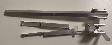
my "crash test", although encouraging, showed a somewhat "hesitant" behavior: the carriage on eccentricities flowed easily, which is not unusual with non-recirculating bearing, but the movement was not as smooth as I like it. Mike56, who had some initial problems with CG placement, gave me helpful hints and I began to notice several other details to improve. In short, I built a second carriage: the improvements are small, almost not measurable, but the cantilever moves better, and this is important.
(drawings - attachment)
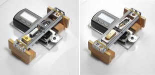
VTF VARIATIONS (digital scale setup - attachment)
The first A cart, reassembled, and the second B cart show not much difference; indeed the former perhaps moves better, due a single CW (instead of two different ones), longer base ("headshell") and more building precision
A cart - H / VTF
0 / 1.58 - 0.5 / 1.56 - 1 / 1.55 - 1.5 / 1.58 - 2 / 1.60 - 2.5 1.62 - 3 / 1.75 - 3.5 / 1.73 - 4 / 1 , 72
B cart - H / VTF
0 / 2.22 - 0.5 / 2.19 - 1 / 2.22 - 1.5 / 2.23 - 2 2.25 - 2.5 / 2.18 - 3 / 2.20 - 3.5 2.08 - 4 / 2 ,10
The digital scale measurements confirm the first rough tests done: very small changes in VTF due height (only 0,15 gr ca on severe warps >3mm) and a quite good repeatabilty (however worse than a good pivoted)
FRICTION - STICTION (sine bar set up - attachment)
A cart Total weight = 48 gr
friction - runs with a tilt of a 0,35 height / 300mm rail. angle = 0°2'17" = 0,038 decimal --- μ =0.00066
stiction - starts with a tilt of a 0,75 height / 300mm rail. angle = 0°5'10" = 0,086 decimal --- μ =0.0015)
B cart Total weight = 46 gr
friction - runs with a tilt of a 0,40 height / 300mm rail. angle = 0°2'17" = 0,038 decimal --- μ =0.00066
stiction - starts with a tilt of a 0,65 height / 300mm rail. angle = 0°5'10" = 0,086 decimal --- μ =0.0015)
A bit worse than the CorkScrew cart ones - and I was so proud to have reached 0.1 and 0.04 of parallelism! - Evidently some more play with a self centering rail doesn't hurt. and less weight too! (39 vs 48 gr)
The two carts have practically the same (average) measures, but not the same behavior - rolls unevenly the first A cart, really smoothly the second one, the B cart - an acceptably centered CG seems really to count a lot.
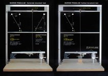
INVERSE PENDULUM (inverse pendulum set up - attachment)
as known, the pendulum measures are only stiction measures, and even less reliable than those with the sinebar (more measures for an acceptable average) However, their observation is very useful to better understand their behavior on a leveled rail.
(only for the cart B - the measurements of cart A do not give measurable average differences)
B cart Horizontal movement
Total weight = 46 gr
displacement S = 0,0028 m
Θ (angle = 4,59°
H (mg height) = 0,00112
U (pot. energy) = 5,048-5
F (friction) = 0,0018 N
B cart Vertical movement
Total weight = 46 gr
displacement S = 0,0032 m (42- ca 10mm)
Θ (angle = 5,24°
H (mg height) = 0,0015
U (pot. energy) = 6,596-5
F (friction) = 0,0020 N
CRASH TEST (3+3 MP4 video zipped - attachments)
And now, for your amusement. the usual "crash test videos". (Eccentricity = 1,5 mm - Warp = 3mm - far beyond RIIA spec.)
In the B cart there is a visible improvement compared to A, especially in the horizontal movement.
Seem not so bad to me, and the tracking of average LPs with normal defects is also smooth and satisfactory.
ciao a tutti - carlo
sorry for the delay - but there was a good reason, beyond my laziness
my "crash test", although encouraging, showed a somewhat "hesitant" behavior: the carriage on eccentricities flowed easily, which is not unusual with non-recirculating bearing, but the movement was not as smooth as I like it. Mike56, who had some initial problems with CG placement, gave me helpful hints and I began to notice several other details to improve. In short, I built a second carriage: the improvements are small, almost not measurable, but the cantilever moves better, and this is important.
(drawings - attachment)
VTF VARIATIONS (digital scale setup - attachment)
The first A cart, reassembled, and the second B cart show not much difference; indeed the former perhaps moves better, due a single CW (instead of two different ones), longer base ("headshell") and more building precision
A cart - H / VTF
0 / 1.58 - 0.5 / 1.56 - 1 / 1.55 - 1.5 / 1.58 - 2 / 1.60 - 2.5 1.62 - 3 / 1.75 - 3.5 / 1.73 - 4 / 1 , 72
B cart - H / VTF
0 / 2.22 - 0.5 / 2.19 - 1 / 2.22 - 1.5 / 2.23 - 2 2.25 - 2.5 / 2.18 - 3 / 2.20 - 3.5 2.08 - 4 / 2 ,10
The digital scale measurements confirm the first rough tests done: very small changes in VTF due height (only 0,15 gr ca on severe warps >3mm) and a quite good repeatabilty (however worse than a good pivoted)
FRICTION - STICTION (sine bar set up - attachment)
A cart Total weight = 48 gr
friction - runs with a tilt of a 0,35 height / 300mm rail. angle = 0°2'17" = 0,038 decimal --- μ =0.00066
stiction - starts with a tilt of a 0,75 height / 300mm rail. angle = 0°5'10" = 0,086 decimal --- μ =0.0015)
B cart Total weight = 46 gr
friction - runs with a tilt of a 0,40 height / 300mm rail. angle = 0°2'17" = 0,038 decimal --- μ =0.00066
stiction - starts with a tilt of a 0,65 height / 300mm rail. angle = 0°5'10" = 0,086 decimal --- μ =0.0015)
A bit worse than the CorkScrew cart ones - and I was so proud to have reached 0.1 and 0.04 of parallelism! - Evidently some more play with a self centering rail doesn't hurt. and less weight too! (39 vs 48 gr)
The two carts have practically the same (average) measures, but not the same behavior - rolls unevenly the first A cart, really smoothly the second one, the B cart - an acceptably centered CG seems really to count a lot.
INVERSE PENDULUM (inverse pendulum set up - attachment)
as known, the pendulum measures are only stiction measures, and even less reliable than those with the sinebar (more measures for an acceptable average) However, their observation is very useful to better understand their behavior on a leveled rail.
(only for the cart B - the measurements of cart A do not give measurable average differences)
B cart Horizontal movement
Total weight = 46 gr
displacement S = 0,0028 m
Θ (angle = 4,59°
H (mg height) = 0,00112
U (pot. energy) = 5,048-5
F (friction) = 0,0018 N
B cart Vertical movement
Total weight = 46 gr
displacement S = 0,0032 m (42- ca 10mm)
Θ (angle = 5,24°
H (mg height) = 0,0015
U (pot. energy) = 6,596-5
F (friction) = 0,0020 N
CRASH TEST (3+3 MP4 video zipped - attachments)
And now, for your amusement. the usual "crash test videos". (Eccentricity = 1,5 mm - Warp = 3mm - far beyond RIIA spec.)
In the B cart there is a visible improvement compared to A, especially in the horizontal movement.
Seem not so bad to me, and the tracking of average LPs with normal defects is also smooth and satisfactory.
ciao a tutti - carlo
Attachments
-
 CS-FP CART A-B.jpg128.9 KB · Views: 187
 -
 FP A + B-SCALE.jpg208.2 KB · Views: 179
 -
 FP sine bar 2.jpg339.2 KB · Views: 187
 -
 FLAT P PENDULUM.jpg317.9 KB · Views: 193
 -
FP CART A ECC.zip805 KB · Views: 90
-
FP CART A WARP .zip881.1 KB · Views: 90
-
FP CART A W+E .zip855.1 KB · Views: 78
-
FP CART B ECC.zip924.8 KB · Views: 82
-
FP CART B WARP.zip838.4 KB · Views: 86
-
FP CART B W+E.zip829.8 KB · Views: 83
Carlo, now we just need to see some excellent photos of the whole, very neat and excellent realisation please!CORKSCREW MK2 MEASURES -(#4560)
sorry for the delay - but there was a good reason, beyond my laziness
my "crash test", although encouraging, showed a somewhat "hesitant" behavior: the carriage on eccentricities flowed easily, which is not unusual with non-recirculating bearing, but the movement was not as smooth as I like it. Mike56, who had some initial problems with CG placement, gave me helpful hints and I began to notice several other details to improve. In short, I built a second carriage: the improvements are small, almost not measurable, but the cantilever moves better, and this is important.
(drawings - attachment)
VTF VARIATIONS (digital scale setup - attachment)
The first A cart, reassembled, and the second B cart show not much difference; indeed the former perhaps moves better, due a single CW (instead of two different ones), longer base ("headshell") and more building precision
A cart - H / VTF
0 / 1.58 - 0.5 / 1.56 - 1 / 1.55 - 1.5 / 1.58 - 2 / 1.60 - 2.5 1.62 - 3 / 1.75 - 3.5 / 1.73 - 4 / 1 , 72
B cart - H / VTF
0 / 2.22 - 0.5 / 2.19 - 1 / 2.22 - 1.5 / 2.23 - 2 2.25 - 2.5 / 2.18 - 3 / 2.20 - 3.5 2.08 - 4 / 2 ,10
The digital scale measurements confirm the first rough tests done: very small changes in VTF due height (only 0,15 gr ca on severe warps >3mm) and a quite good repeatabilty (however worse than a good pivoted)
FRICTION - STICTION (sine bar set up - attachment)
A cart Total weight = 48 gr
friction - runs with a tilt of a 0,35 height / 300mm rail. angle = 0°2'17" = 0,038 decimal --- μ =0.00066
stiction - starts with a tilt of a 0,75 height / 300mm rail. angle = 0°5'10" = 0,086 decimal --- μ =0.0015)
B cart Total weight = 46 gr
friction - runs with a tilt of a 0,40 height / 300mm rail. angle = 0°2'17" = 0,038 decimal --- μ =0.00066
stiction - starts with a tilt of a 0,65 height / 300mm rail. angle = 0°5'10" = 0,086 decimal --- μ =0.0015)
A bit worse than the CorkScrew cart ones - and I was so proud to have reached 0.1 and 0.04 of parallelism! - Evidently some more play with a self centering rail doesn't hurt. and less weight too! (39 vs 48 gr)
The two carts have practically the same (average) measures, but not the same behavior - rolls unevenly the first A cart, really smoothly the second one, the B cart - an acceptably centered CG seems really to count a lot.
INVERSE PENDULUM (inverse pendulum set up - attachment)
as known, the pendulum measures are only stiction measures, and even less reliable than those with the sinebar (more measures for an acceptable average) However, their observation is very useful to better understand their behavior on a leveled rail.
(only for the cart B - the measurements of cart A do not give measurable average differences)
B cart Horizontal movement
Total weight = 46 gr
displacement S = 0,0028 m
Θ (angle = 4,59°
H (mg height) = 0,00112
U (pot. energy) = 5,048-5
F (friction) = 0,0018 N
B cart Vertical movement
Total weight = 46 gr
displacement S = 0,0032 m (42- ca 10mm)
Θ (angle = 5,24°
H (mg height) = 0,0015
U (pot. energy) = 6,596-5
F (friction) = 0,0020 N
CRASH TEST (3+3 MP4 video zipped - attachments)
And now, for your amusement. the usual "crash test videos". (Eccentricity = 1,5 mm - Warp = 3mm - far beyond RIIA spec.)
In the B cart there is a visible improvement compared to A, especially in the horizontal movement.
Seem not so bad to me, and the tracking of average LPs with normal defects is also smooth and satisfactory.
ciao a tutti - carlo
M
 🎉
🎉I don't know why. All the videos look like this on my Mac. Is it possible to post all the videos on Youtube?

Cute, seems coming from Mars!
Sorry, no youtube. Who wants to see this stuff has to make the effort to follow our threads, imo.
simply zipped .mp4 (conversion from .avi) due DiyAudio allowed formats
c
Sorry, no youtube. Who wants to see this stuff has to make the effort to follow our threads, imo.
simply zipped .mp4 (conversion from .avi) due DiyAudio allowed formats
c
For me its very simple audiostar, this is a diy forum and i make my diy versions without machine tools, no chance i can make a servo arm and with lots of help from folk on the forum i have been able to make a passive arm that meets lots of folks aspirations, if anyone can make one like Carlo's and compare it!, that would be fantastic!Linear servo tonearm vs linear non servo tonearm. What are the advantages or disadvantages?
The servo may be perfectly valid but I would be interested to measure and hear if its better? I have posted measurements, Carlo has as well, lets see how we might improve the breed with some other ideas? has anyone got measurements of a servo linear/linear to compare please?
All the best M
For me it is not that simple. Mike is right , servos have a tendency to be more complicated because of the needed motor drive, but not necessary bigger demands to your mechanical workshops machinery.Linear servo tonearm vs linear non servo tonearm. What are the advantages or disadvantages?
There are two types of servo arms as I see it. All of the commercial servo arms (as far as I know) fall into the first category: Error correcting servo arms. They are in principle normal pivoted arms on a sledge that is controlled by the servo system. A detecting system looks at the angle between the arm and the sledge and as soon as the angel differs from 90 deg, the servosystem corrects this. The advantage would be vs a pivoted arm, that the cartridge is always at 90 deg (well lies is maybe the problem) whereas the pivoted arm always has a angle error except for two positions on the record. But as the servo arm is an error correction system, it needs an error before it can correct that, which means it constantly pops in and out of an error and that is , in some arms anyway, something you can hear.
There is a thread where Warrjon describes his efforts to make such an arm:
https://www.diyaudio.com/community/threads/diy-servo-driven-linear-tonearm.357301/page-4
The pivoted arms has a theoretical advantage over passive linear trackers in that the side forces on the PU cantilever is less. In the passive arms you always have a sledge of some kind that the cantilever has to push in order to work properly and the friction and the mass of this sledge is directly transformed into side forces on the cantilever. So the big problem here is to reduce the mass and the friction /stiction.
The second category of servo arms tries to deal with this. This type of arm is always at 90 deg to the groove so no error correction here. As far as I know there is only one such arm and I not sure that it has become a commercial arm yet.
https://www.diyaudio.com/community/threads/a-revolutionary-pivoting-tangential-tone-arm.327684/
This is kind of a strange beast as it is a straight tracker that keeps the headshell @90 deg, but has a pivoting servosystem . The movement of the headshell should be helped by the drag of the groove on the cantilever as well as the side force. I am not sur I understand why, though...
I , personally, would like to see a servo arm that uses a very small passive linear sledge on a rail that only has to move a couple of mm and then correct the placement of this rail so the sledge is always near the middle of the rail. The advantages of such a system as I see it: Always 90 deg. no error correction a very short rail could be made with less friction, stiction and mass and because of the smaller physical dimension may also easier to reduce vibrational energy (?)
This is all theory of course.
And one of the joys of making DIY things is just doing it , not necessarily making the best............
- Home
- Source & Line
- Analogue Source
- DIY linear tonearm