Hi Mike . The eccentricity indeed makes for some speed variations that are clearly audible. But that is true in a tangential arm as well. Listen to a sustained organ or piano tone on an eccentric record. That sounds awful.Hi Gents, reflecting on the speed errors of a pivoting arm on its arc, i feel the desription assumes zero eccentricity, as there will always be some eccentricity, the arm will be going in and out the eccentricity difference each revolution, so that will multiply the earlier calculation of variation by 2 for the go and return and by the number of grooves for the entire record. thinking only about each revolution, and indeed the perhaps small part where there is eccentricity, is the speed variation discernible as a variation in pitch? if people with absolute pitch can discern 0.1% variation, does this suggest a problem or not?
M
That was my concern, but if the radius Ralphs arm is following is moving at a constant speed, it is not audible just a constant and very small speed error. For people with absolute hearing this can be corrected by adjusting the TT speed...
Exactly. The servo is not correcting the angle but simply there to extend the path of the tracking. Theoretically, if the headshell were 4 inches wide with a curved track a la Thales semi-circle (or a straight track in line with the radius), you wouldn't even need the servo.Yours is not an ERROR CORRECTING servo and that is what I like about it and why I am investigating to make a strictly tangential tracker, servo assisted, but not error correcting
Interesting with the curved headshell. But even more interesting that this idea of the non error correcting servo has been so much misunderstanded and put down by the DIY community.Exactly. The servo is not correcting the angle but simply there to extend the path of the tracking. Theoretically, if the headshell were 4 inches wide with a curved track a la Thales semi-circle (or a straight track in line with the radius), you wouldn't even need the servo.
It really doesn't matter to say the servo is not correcting the angle or the servo is correcting the angle. It is the same thing with different sayings. It isn't incorrect to say the servo is correcting the angle, z, in the diagram.

Ralf's arm is a variant of Birch-style arms with an offset angle. It has tracking errors, too. In fact, I would say the tracking errors are not minimized from his drawing. Does the offset angle help to reduce tracking errors? I am not sure at this moment.
My other concern is the efficiency of the small linear bearing. I still don't see the need for a small linear rail unless the servo doesn't allow to move backward if the eccentricity does exist.
I am sorry it doesn't seem to be the right place to discuss Ralf's arm.
Last edited:
Once again. There are two different kind of servo arms. The vast majority are correcting a tracking angel error and only one, Ralphs , (and the one I have suggested ) does NOT correct a tracking angel error because the floating head shells are following a perfectly straight line and it is only the POSITION in this headshell that is corrected in the servo systemIt really doesn't matter to say the servo is not correcting the angle or the servo is correcting the angle. It is the same thing with different sayings. It isn't incorrect to say the servo is correcting the angle, z, in the diagram.
View attachment 1017745
Ralf's arm is a variant of Birch-style arms with an offset angle. It has tracking errors, too. In fact, I would say the tracking errors are not minimized from his drawing. Does the offset angle help to reduce tracking errors? I am not sure at this moment.
My other concern is the efficiency of the small linear bearing.
Does it matter? No. As I said before, a Birch-style arm needs at least two linkages. Ralf's arm has only one linkage. Its constraint is built in the servo. Let's forget the rail for a moment. So, the servo which acts as a constraint( or 2nd linkage) is correcting the angle. Correcting angle can adjust the position of the headshell, too. I simply don't see it matters.Once again. There are two different kind of servo arms. The vast majority are correcting a tracking angel error and only one, Ralphs , (and the one I have suggested ) does NOT correct a tracking angel error because the floating head shells are following a perfectly straight line and it is only the POSITION in this headshell that is corrected in the servo system
Well this must be for ralph to explain. I am not enough into the way Ralphs arm works to be absolutely sure ... BUT What I suggest does not correct any errors ...
HO-HO-O. I rather like the look, and the right turntable can handle O gauge.Also in my opinion, the straight line tone arms like the Rabco etc overwhelm the average turn table. Some of them look like an HO model railroad car sitting on the side of the turn table. (Nothing personal Ray K) sic.
Sincerely,
Ralf
Just for the record (pun intended):Hi koldby,
The styli of all tone arms travel either on a straight or a curved path. Whichever it is, is completely irrelevant. The only important requirement is that, the cantilever center line makes an angle of 90 degrees with a radius of random length between the start and the end of the modulated groove. Back in the 1980s, when I designed my first pivoting tangentially tracking tone arm, I realized that any pivoting tone arm's stylus moves "around" the LP's center by ~ 16 degrees clockwise depending upon the basic geometry of the tone arm, thus adding to the length of time it takes to play a particular piece of music. So I did the math and found this added length of time to be ~ 6 milliseconds! Next, I looked up what the accuracy of a quality metronome was and it didn't come anywhere near 6 milliseconds! If Doc Watson or the Berlin Philharmonic Orchestra played the same piece of music twice in a row, they would not be able to do that within 6 milliseconds. 🙂 I am sure others before me have discovered the above.
Sincerely,
Ralf
I did the math also. For a tonearm with 240 mm effective length and 222.75 mm mounting distance, with the last groove at 60 mm from the spindle the added time is 0.11 sec at 33.3 RPM.
Hi koldby, Hi super10018,Well this must be for ralph to explain. I am not enough into the way Ralphs arm works to be absolutely sure ... BUT What I suggest does not correct any errors ...
My tone arm's tangential position is solely controlled by a set of two cams and their cam followers. They are not shown in the drawing posted by super10018. The geometry is perfect and there is no tracking error! The oblong component at the end of the tone arm, I call the cradle. It supports five miniature ball bearings to support the "floating" head-shell for straight-line motion to keep the cartridge's cantilever tangent to a concentric circle of random diameter within the limits of the beginning and the end of the modulated groove of an LP record. The offset cradle/head-shell deliberately introduces the "inward force" so that the tone arm becomes "self propelled" across the surface of the LP. Because the tone arm and the head-shell move independently of each other, some means of preventing a collision between the tone arm and the head-shell had to be devised. That is the purpose of the "servo". It simply controls the "inward force". You might call it electronic anti skating!
There is another reason for off-setting the cradle/head-shell of my tone arm: All pivoting tangentially tracking tone arms require that their pivots be moved by a certain distance. Off-setting the cradle/head-shell reduces that distance by ~50% as opposed to a non off-sett cradle/head-shell.
Sincerely,
Ralf
Turn it at 90 degree, then you can dispose of the parallelogram with the four bearings.just for fun
would be possible a wheel-less LTA ? (not a PLTA)
c
What remains, is a suitable linear bearing. 🙂
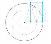
The red dotted line in #4,611 must be a linear bearing.is a suitable linear bearing.
Something like this? describes an arc not a line
c
But when you have a good linear bearing, you don't need the parallelogram at all.
What remains is a linear tracker.
The red dotted line in #4,611 must be a linear bearing.
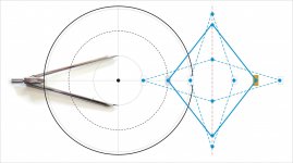
No there is no need: i.e. the photo of my Kern compass is there because, like many others, uses just a cam to maintain the alignment.
My sketch is clearly a provocation, not a solution, with all those pivots it would surely have serious problems to work.
Since many are looking for clever geometries for PLTs, why not also for our linear ones?
carlo
A Gerhard turntable from the 70's used a similar idea. Narrower parallelogram though.is a suitable linear bearing.
Something like this? describes an arc not a line
c
https://www.vinylengine.com/library/garrard/zero-100.shtml
Sorry. Seems that sometimes my sketches are even less understandable than my English. I hope this mockup is clearer (even if the mechanism is much less sophisticated than the KERN compass). But what's important is to understand each other
I think the old Garrard (and clones) worked more like the parallelogram shown at #4614.
I think the old Garrard (and clones) worked more like the parallelogram shown at #4614.
Attachments

- Home
- Source & Line
- Analogue Source
- DIY linear tonearm