Babowana said:
I agree with you, Tony.
I also like to recomment 5W rating
because the current per source R (R5 and 6) is 0.66/.47=1.4A
and dissipation per source R is 1.4x1.4x1.2=2.4W
Considered the 3W rating having only mere margin.
Correct, one has also to consider that resistor are more noisy when you run them above 1/2 their rating. Thermal noise, that is.
So what would happen if I hooked my headphones up to the F2? They are single drivers, after all. 32 ohm and 300 ohm
Just test them, hear the music and report back if you liked it, no problem or hazards involved assuming you have a vol control in front of your amp
Hi Babowana,
Sorry, I'm using PNP BC560C not BC550C. It has three times higher hfe than ZTX550. Is it better in this application? Will using darlington transistor produces much better result since it has much higher hfe?
Also does it helps to use lower noise pnp transistor in this application as BC560C is advertised as low noise transistor?
Thanks.
Ipanema said:Sorry, I'm using PNP BC560C not BC550C. It has three times higher hfe than ZTX550. Is it better in this application? Will using darlington transistor produces much better result since it has much higher hfe?
Hi Ipanema
As Papa is watching, I feel nervous in responding these kinds of questions.
Nevertheless . . . as far as I understand, the PNP TR works as an on-off switch referring to the voltage across (your) R2, to maintain the constant V across it. This probably means that if the TR has higher current gain, the on-off switching speed might be getting faster, lowering the ripple voltage in R2. If so, it is preferable.
Meanwhile, the faster on-off switching means that base of the TR is seeing very high ac input frequency, so that it might result in some stability problem due to pahse shifting. Therefore, I think we need to prepare spare parts of about .001uF (between B and C) compensation caps just in case.
I hardly think that the darlington is necessary.
Hi Babowana,
Thanks for the explanation. I will build the amp this week. Hope that it works well.
Thanks.
🙂
Thanks for the explanation. I will build the amp this week. Hope that it works well.
Thanks.
🙂
Ipanema said:Thanks for the explanation. I will build the amp this week. Hope that it works well.
You are very welcome. I am sure that you will soon have a great amp. By the way, when you finish, could you kindly post measured dc-voltages for info . . . ?
Pllease excuse the somewhat silly question, but I'm trying to understand the theory of this amplifier: If i put a resistor in series with the speaker, should I experience any changes? Because from what I read I expected there to be no change at all, yet out of bored experimentation I put a 47ohm resistor in series with the speaker and at the least it seems to reduce the volume slightly
Generally you are not looking to put the resistor in series
with such an amplifier, but in parallel across the amp or
speaker terminals.
Yes, when you do that the gain goes down a bit, but the
frequenciy response and damping of the speaker will alter.
Presumably there is some optimal value of resistance and/or
other loading.
😎
with such an amplifier, but in parallel across the amp or
speaker terminals.
Yes, when you do that the gain goes down a bit, but the
frequenciy response and damping of the speaker will alter.
Presumably there is some optimal value of resistance and/or
other loading.
😎
Hey Nelson, thanks for the reply (and although I've said it before, thanks for the firstwatt)
My question and experiment was more out of curiosity, rather than expecting to have positive results. From what I read I expected it to make zero difference to put a resistor in series, so I was a little surprised that it did make a difference. In hindsight I guess its not too surprising because at the least the resistor will burn off some of the music power as heat.
So is this correct: In a normal amplifier if the series resistance is changed, this affects the amount of current provided by the amplifier via ohms law, and thus this affects how loud the speaker will play . On a firstwatt, regardless of series resistance, the current provided will remain the same, and the only reason that my speaker volume changed was due to the resistor consuming some of the current?
edit: for the record, I removed the 47 ohm resistor bank in parallel with the speaker because I read that it would improve bass by changing the damping (and my speakers are a tad bass ligh). I dunno if it helped or not and I dunno if I'll keep it like this or not
hugz said:On a firstwatt, regardless of series resistance, the current provided will remain the same, and the only reason that my speaker volume changed was due to the resistor consuming some of the current?
My understanding . . .
A good voltage source is a weak current source at the same time.
Or, a good current source is a weak voltage source.
They do a crossover, but on the unequal quality.
Sorry for interupting your conversation with Papa . . . 🙂
hugz said:So is this correct: In a normal amplifier if the series resistance is changed, this affects the amount of current provided by the amplifier via ohms law, and thus this affects how loud the speaker will play . On a firstwatt, regardless of series resistance, the current provided will remain the same, and the only reason that my speaker volume changed was due to the resistor consuming some of the current?
As an approximation, yes. The F1 and F2 are not perfect
current sources, having high output impedances instead of
infinite.
😎
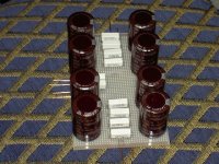
I'm still waiting for my sinks from conrad in oz but I have made progress on the ps.
BTW I beleive there are some polarity issues on the ps drawing you produced hugz. Specifically I'm not sure if the caps are shown with reverse polarity and the lhs positive out maybe coming from the wrong side of the 1R resistor bank????
I hope to use this matrix board method for the amp modules..its nearly as much fun as p2p with valves....
Regards
Ed
Attachments

vitalstates said:BTW I beleive there are some polarity issues on the ps drawing you produced hugz. Specifically I'm not sure if the caps are shown with reverse polarity and the lhs positive out maybe coming from the wrong side of the 1R resistor bank????
I hope to use this matrix board method for the amp modules..its nearly as much fun as p2p with valves....
Regards
Ed
Eep you're right. the cap polarity was just a mistake in my drawing, but one of my channels was wired wrong :/ Thanks for pointing that out! I think it helped with my noise issues 🙂 the drawing's been fixed
hugz said:So what would happen if I hooked my headphones up to the F2? They are single drivers, after all. 32 ohm and 300 ohm
apassgear said:Just test them, hear the music and report back if you liked it, no problem or hazards involved assuming you have a vol control in front of your amp
Okay I got my headphones back from a friend today so I hooked them up to my f2. Initially it hummed a bit and was too loud, so after playing around I added some resistors in parallel with the headphones which seemed to reduce the volume (i'm no EE so this was all just guesswork). Eventually I realised that I should just reconnect the damping network which i think is 15 ohms in parallel with the speaker (three 47ohm in parallel)?
By this stage I was too lazy to remove the extra resistors I added in parallel (just one extra 47 ohm by this stage), so for this reason all I can say is that headphones work fine with 47 ohm added in parallel to them. I'm gonna assume that they work fine without the extra resistor too.
I used sennheiser hd580 (300 ohm) and alessandro ms2 (32 ohm) and they both seem fine. It seems that the f2 can be used as a nice little (big) headphone amp
edit: oh and because I cant find any of my spare headphone cables, I didn't recable either of the headphones to separate the grounds like i was planning to. It doesn't seem to matter, however I think it means that it's in reverse polarity since the amp's signal is supposed to go to speaker negative, but I had to make it go to positive or else both of the channels would be merged together in the shared negative of the hedphone cable
You can easily load the output of the amp with any low value
resistor you like to get the gain you want. Go ahead and try
values like 8 and 4 ohms.
😎
resistor you like to get the gain you want. Go ahead and try
values like 8 and 4 ohms.
😎
Vix said:Has anyone tried F2 lite? F2 with lightbulbs? How will it behave compared to a "normal" F2?
Depends on the bulb resistance and the current you bias at.
With a 16 ohm bulb at about 2.5 to 3 amps you get the same
basic performance (and you don't need the output resistors
except to bleed DC) and IMHO the bulb sounds better, although
it may merely be that I like to look at it glow.
😎
Hi,
If I understand correctly, F2 with a 16 ohm lightbulb is going to have around 16 ohm output impedance? (actually slighly less than that, assuming we connect 100 ohm bleeder resistor, as was done in Zens).
Another point it brings is the correct DC value at the drain of mosfet. If the PSU voltage is around 40, then, should it be set at half that value, or actually less (12 to 15v) as was the case with Zen lite? I guess it will work both ways, but which is the "proper" one here?
(I'm thinging about symmetrical clipping, since we are using a bulb instead of a CCS)
Thank you very much
Vix
- Home
- Amplifiers
- Pass Labs
- DIY F2 clone