apassgear said:
Thanks for the reply Babo🙂
On my amps I also use wirewounds as source resistors but was wondering why others like Nelson avoid using them on this position and though it might be because of inductance and or sonic reasons.
you know how often Papa sez :"I have them plenty in stock"
my guess is that this reason is at least equally important as possible sonic benefits
if any
in crap designs everything is too much important........😀
The inductance in wire wound resistors can be a problem in terms of stability. It is generally too small to cause sonic trouble.
That said, there are so many good non-inductive resistors out there, why use the inductive ones? The only place I can see any benefit is in, say, a CRC filter in a power supply. Even then, the amount of inductance is so minor as to be of little or no benefit.
Grey
That said, there are so many good non-inductive resistors out there, why use the inductive ones? The only place I can see any benefit is in, say, a CRC filter in a power supply. Even then, the amount of inductance is so minor as to be of little or no benefit.
Grey
GRollins said:why use the inductive ones?
The best resistor will be the one having only resistance
My resonse is just to indicate that
the wire wound Source R (0.21-0.47) is "also" ok
If I have them, I would like to use them
I did not check small or micro details
But I do not see any problem in using them
Regards 🙂
Hi Veteran,
Can we see an image of the back side? Are you going to be doing a group buy? I am interested in a set. Thanks.
James
Can we see an image of the back side? Are you going to be doing a group buy? I am interested in a set. Thanks.
James
Sorry for the noob question, but what type of caps may be used for the various positions (eg metal film, electrolytic etc). At the moment I'm guessing that c3 and c4 can be electrolytic, and c1, c2, c5 are metal film?
I have some 10uf paper in oil caps lying around, could they be used for c5 (if there's any benefit over metal film)? Also, can electrolytic be used in c1, c2, c5 because that's slightly more convenient than metal film
Sorry again for such noob questions, but on the bright side I'll soon be done and there will be another f2 in the world!
C3, C4 are definitely electrolytes.
Avoid electrolytes for C1, C2 as they are in the signal path and said to sound less good.
I used polyester MKT series but polypropylene should even be better.
As for C5, I believe your paper in oil will do just fine if the minimum voltage rating is adequate.
/Hugo
Avoid electrolytes for C1, C2 as they are in the signal path and said to sound less good.
I used polyester MKT series but polypropylene should even be better.
As for C5, I believe your paper in oil will do just fine if the minimum voltage rating is adequate.
/Hugo
Thanks Hugo
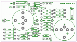
For everyone, here is my board layout. I was hoping someone would be able to check over it quickly to make sure it's laid out properly before I switch the amp on. It looks right to me, but I'm fairly new to this and doing the layout has been a headache.. plus it cost me $45 to ship the parts to austraila! I don't wanna fry it this quickly and have to order more!
If it's right, some newbies may find it helpful in their builds. It's just designed to use stripboard/matrixboard
Thanks in advance for anyone who is able to help out.
An externally hosted image should be here but it was not working when we last tested it.
I found a mistake on my own board :/ here is the updated one
An externally hosted image should be here but it was not working when we last tested it.
Looks fine to me if node just below the emitter of the transistor is connected to the supply.
/Hugo
/Hugo
Hi,
I want to build this amplifier for my D58 ES. I have built some tube amplifiers but it's my first mos amplifier so i have some questions:
About resistors, the R2 value is 221 Ohm. Is a 220 ohm OK?
There is 2,21 k or 47,5 Ohm. I'm surprised. Is it possible to put 2,2K for R21 or 47 Ohm for R3 for example?
For the power supplie, i want to built one like the F1, is it OK or is it better to wait the N.Pass article?
Thank's
A Bientôt
Bruno
du bonnieure said:Hi,
I want to build this amplifier for my D58 ES. I have built some tube amplifiers but it's my first mos fet amplifier so i have some questions:
About resistors, the R2 value is 221 Ohm. Is a 220 ohm OK?
There is 2,21 k or 47,5 Ohm. I'm surprised. Is it possible to put 2,2K for R21 or 47 Ohm for R3 for example?
For the power supplie, i want to built one like the F1, is it OK or is it better to wait the N.Pass article?
Thank's
A Bientôt
Bruno
for resistors -just do as you wrote
for supply-it's your call
Yes its possible. just use the closest value you can get. I am sure the F1 supply is good enough for the F2 also🙂There is 2,21 k or 47,5 Ohm. I'm surprised. Is it possible to put 2,2K for R21 or 47 Ohm for R3 for example?
Steen🙂
Hi,
has anybody produced any pcbs? I know it can be p2p-ed but I always end up screwing up somewhere and wasting more time than I have.
TIA
Giulio
has anybody produced any pcbs? I know it can be p2p-ed but I always end up screwing up somewhere and wasting more time than I have.
TIA
Giulio
AKAIK not but then again, you have no idea how rewarding p2p can be in this simple design.
/Hugo
/Hugo
Okay the basic PSU and one channel of my F2 is done!! A few questions though.. (you saw it coming)
1) There's a constant (but reasonably quiet) hum going on. However I haven't yet connected up the 0.0033uf cap in the F1 PSU (out of laziness because it's legs are too small to do p2p at the moment). Is this constant hum likely caused by this, or something simple such as transformer placement? Or would such a hum be caused by an actual mistake? Previously I had removed the earth and the hum was gone. Also, the hum is gone if its using a discman as source, so i'm worried it could be a ground loop or something (except my source and amp are both on the same outlet)
2) In the 240v F1 PSU how is "TH" wired (I'm using a 240v 18-0-18 transformer with two input wires and 4 output wires)
3) Initially we connected the 24V DC wires from the power supply the wrong way (ie positive to negative), which caused a quiet cracking sound and some smoke. We quickly turned it off and corrected the problem, and since then everything seems to be operating fine.. but I'm still paranoid. Is there anything I could've fried? I'm somewhat worried about the ZXT550, because...
4) Out of curiosity I hooked up my very cheap 3-way sony bookshelf speakers expecting them to sound totally weird... but they sounded totally FINE. Again, I'm paranoid. Could my amp be operating in normal voltage mode somehow? (fried ztx?) or do my sony's just lack a proper xover?
5) How to set the bias? Currently I'm connecting the multimeter to the GND and the opposite leg of the output capacitor (ie the leg thats NOT going to speaker output) and setting the trimpot until I get a reading of half the PSU voltage (ie half of 24v). Correct?
Thanks for the help. Here's a photo of it in action
An externally hosted image should be here but it was not working when we last tested it.
hugz said:Okay the basic PSU and one channel of my F2 is done!! A few questions though.. (you saw it coming)
1) There's a constant (but reasonably quiet) hum going on. However I haven't yet connected up the 0.0033uf cap in the F1 PSU (out of laziness because it's legs are too small to do p2p at the moment). Is this constant hum likely caused by this, or something simple such as transformer placement? Or would such a hum be caused by an actual mistake? Previously I had removed the earth and the hum was gone. Also, the hum is gone if its using a discman as source, so i'm worried it could be a ground loop or something (except my source and amp are both on the same outlet)
Well for what it's worth I unplugged a dodgy monitor that was on the same power board as the amp and the hum is gone
edit: there's still some background noise but it seems more manageable
I am about to start an F2 build using p2p, please wish me luck chaps......can anybody who might be reading this in the UK recommend a good source for heat sink and chassis parts.
Regards
Ed
Regards
Ed
- Home
- Amplifiers
- Pass Labs
- DIY F2 clone