Thanks for the replies! Very helpful
one more question. What is C5 on the schematic? It just says "10" (unlike all the other caps which say #uf). Is it just 10uf?
one more question. What is C5 on the schematic? It just says "10" (unlike all the other caps which say #uf). Is it just 10uf?
OK-- Kofi's interested...
Anyone got a recommendation on a toroidal power supply and heatsinks for this thing?
Hey-- c'mon man... I only got a few days left at the UN and I still got control of the black helicopters and peacekeeping forces. You need a favor, you got a favor.
Kofi
Anyone got a recommendation on a toroidal power supply and heatsinks for this thing?
Hey-- c'mon man... I only got a few days left at the UN and I still got control of the black helicopters and peacekeeping forces. You need a favor, you got a favor.
Kofi
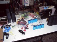
Here is some work in progress.
Toroid is a 250VA 18+18V. Military grade of course. 😉
I would have preferred a bigger one but could not get my hands on it.
Fins are recycled from an old Kustom amp, 16.5 x 12.3 cm.
Wine is a cheap Cabernet, better pictures to follow.
/Hugo
Toroid is a 250VA 18+18V. Military grade of course. 😉
I would have preferred a bigger one but could not get my hands on it.
Fins are recycled from an old Kustom amp, 16.5 x 12.3 cm.
Wine is a cheap Cabernet, better pictures to follow.
/Hugo
Attachments
OK-- Kofi's interested...
Annan,
you traitor, get back to your glasworks.
We'll have to write a letter to Mrs Secretary-General.
Who needs peace !
We want a lot of noise,.. and parades.
Hugo,
got a picture of your Fostex for Peeping Tom ?
My pleasure. 🙂
http://www.diyaudio.com/forums/showthread.php?s=&threadid=88557&highlight=
I'm determined to make them sound nice and hopefully an F2 will help me.
/Hugo
http://www.diyaudio.com/forums/showthread.php?s=&threadid=88557&highlight=
I'm determined to make them sound nice and hopefully an F2 will help me.
/Hugo
Off Topic a bit
My fonkens and bifonkens sound best with my little EL84 amp. They pretty much suck with my Cambridge Audio SE500. They are not bad with my MiniA (but it has a hum).
I think a well exicuted current source amp will be the ticket. Nelson's article on fullrange drivers and amps is great, cause he spends time talking about the Fostex drivers.
Good luck
Nice P to P by the way.
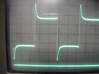
Obviously, I must have done something wrong.
This is the square wave at +/-1Khz, speakers attached, low output power.
I would be thankful if someone could tell me how to set P1. On a certain point, bias is set at +/- 2.7A. I can still increase P1 but bias stays put.
/Hugo
This is the square wave at +/-1Khz, speakers attached, low output power.
I would be thankful if someone could tell me how to set P1. On a certain point, bias is set at +/- 2.7A. I can still increase P1 but bias stays put.
/Hugo
Attachments
Hugo, you want to adjust P1 to get a reading of one half, of the DC-supply voltage just in front of the outputcap! Connect your DVM to GND and in front of the outputcap and adjust P1 to get the correct reading.
Steen🙂
Steen🙂
Thanks Steen. Done. 🙂
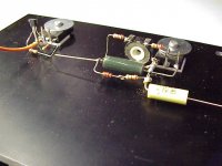
I used very common components, no 1% resistors except R3 which is 47 ohm instead of 47.5.
At the source of Q1 I attached a 7W 0.68ohm and the resistors R23..R26 are replaced by 3 X 0.22ohm.
I can't imagine that this would affect the square wave that much. Or is my imagination off track? 🙂
/Hugo
I used very common components, no 1% resistors except R3 which is 47 ohm instead of 47.5.
At the source of Q1 I attached a 7W 0.68ohm and the resistors R23..R26 are replaced by 3 X 0.22ohm.
I can't imagine that this would affect the square wave that much. Or is my imagination off track? 🙂
/Hugo
Attachments
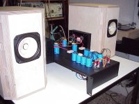
Looking at your picture, those Mosfet's are too close to the top of the heatsinks. I dont mean to be rude or something, but my best guess is, that they will run too hot in that position! My rule of thump is, one third up from the bottom!! BTW turn them upside down.
Steen🙂
Steen🙂
Rude? I wouldn't even think you could be rude.🙂
I could turn the whole construction upside down -I mean the heat sinks- without changing anything. Then, the center of the mosfets would be at 1/4 of the bottom and the pins would point upwards. But why would you turn the mosfets upside down?
/Hugo
I could turn the whole construction upside down -I mean the heat sinks- without changing anything. Then, the center of the mosfets would be at 1/4 of the bottom and the pins would point upwards. But why would you turn the mosfets upside down?
/Hugo
You dont want to turn the mosfet upside/down. What you want is to place the heatsource 1/3 up from the bottom😉 I had a hard time to get convinced about that fact, but finally I did get convinced😀 I guess the hot air rising is the cause🙂But why would you turn the mosfets upside down?
Hugo, dont hesitate to ask further.
Steen😎
So am I right now!! Getting my Aleph-J in the air was really great😀But first I'll enjoy a few nice songs.
Steen😎
Hugo, your progression looks nice. how long did it take? What are the rating on those heatsinks, and how hot do they get?
A general question for everyone.. is 300VA transformer good enough?
Also, how important is mosfet matching? If i want a decently matched pair of mosfets, how many should I buy?
A general question for everyone.. is 300VA transformer good enough?
Also, how important is mosfet matching? If i want a decently matched pair of mosfets, how many should I buy?
I don't know the Rth of the heats sinks I used but found a nice calculator online.
http://www.frigprim.com/
Think in terms of +/-30W per mosfets to dissipate.
As I did everything PtP, it's a constant improvising how to place each part. I like this approach for simple designs because it's much more fun than plugging parts into PCB holes. Sure it takes more time. I guess it took about a whole day spread over a week to assemble.
I used a 250VA transformer and it gets warm but not excessive. 300VA is enough to be real safe.
As for the mosfets, I don't believe any matching should be done. I selected the gain device for highest transconductance.
/Hugo
So, increasing C4 to 15000uF is enough to get a nice slow startup process even if the rail voltage comes up instantly?
That´s interesting news for a project I have in mind, I want to get as high rail voltage as possible (CLC-filtering) out of my surplus transformer so I don´t want to waste 4-5V across a cap multiplier.
That´s interesting news for a project I have in mind, I want to get as high rail voltage as possible (CLC-filtering) out of my surplus transformer so I don´t want to waste 4-5V across a cap multiplier.
- Home
- Amplifiers
- Pass Labs
- DIY F2 clone