Guys, how off the rails am I at this point?

Thermal drift and voice coil baking under DC current?
Thermal drift and voice coil baking under DC current?
Last edited:

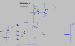
Dual rail, no output caps, no PSU resistor bank ... are you going to build it? I'm very curious how it will sound. What is D1 for? Is it holding the gate voltage high enough to open M1?
At least in the simulations, it behaves the same way. I'm not sure yet whether to go with dual rails like in the F5, or use a capacitance multiplier with regulation. D1 is just there to protect the MOSFET. I'm a bit concerned about thermal drift in the SemiSouth JFETs, but I believe it should be minimal. I’ll test it first using a lab PSU and observe the behaviour.
PS: and if the bench testing turns out successful, I’d make the project modular: separate PCBs for the CCS, the VAS with the SIT, and if I decide to use a capacitance multiplier, it would have its own board as well.
PS: and if the bench testing turns out successful, I’d make the project modular: separate PCBs for the CCS, the VAS with the SIT, and if I decide to use a capacitance multiplier, it would have its own board as well.
Last edited:
easy to sim and hear the difference; just put 100uF from pot wiper to gnd, then remove it
brain on reserve, done some paperwork for tomorrow and, instead of being useful - solving some correspondence duties, I'm clicking in LTS, just to check my 3 gray cells
and yes, what I remember from time when I had something to remember - there is no significant feedback loop in original F2, even if sorta looking opposite
that 100K from mosfet gate to voltage divider is significant in value, so negating whatever voltage swing left in divider
as I said = easy to check, connect or disconnect C3 to GND
in short - no feedback, some additional loading at output just to tame things a little ( make everything more controlled and predictive), that's your CS amp
introduce regular feedback, nature of the beast, no more CS amp
Attachments
Great, thanks for the explanation.
So the higher the value of R6, the higher the amplifier's output impedance, and the more it has a current source character, correct?
In the F2J, R6 was reduced to 8.2k to deal with possible gate leakage from the non-insulated gate of the SemiSouth device. But if the voltage drop across R6 stays below, let's say 0.4V (no signal and once the amp is fully warmed up), would it be safe to increase R6 value, even up to 100k?
Is my understanding correct?
PS. In your circuit R6 is R9.
Last edited:
if you want CS amp, yes, one of the ways is as shown with F2 - no overall feedback, so OLG as high as possible
Pa's resistive loading of output is made to tame things a little, to diminish possible xconductance variation/difference between mosfets etc.
so, yes, "R6" as high as possible, while still maintaining DC parameters stability
if you choose to include input buffer ( as drawn on my napkin back, few posts back) said resistor is not critical at all (being now at JFet gate), buffer taking care of possible gate leakage of output part
Wait a minute, interesting part is here:

It seems like in your CCS you're sneaking in a few electrons together with the photons. Could you explain this hybrid quantum situation, sir?
What kind of wizardry is this?
It seems like in your CCS you're sneaking in a few electrons together with the photons. Could you explain this hybrid quantum situation, sir?
What kind of wizardry is this?
optotransistor is DC coupled to maintain Iq
cap to gate is connected through Zen Amount Pot, so you can adjust modulation of Mu Follower, so changing THD Spectra (in some range) to your liking
ZAP all the way down, full Mu modulation, current contribution close to 50% of sum current, THD Spectra leaning more to PP nature of things and everything
ZAP all the way up, decrease of Mu modulation, current contribution decreased and THD Spectra leaning to more SE nature of things and everything
interesting thing - I have similar trimpot arrangement in Babelfish F8 (F8b, F8m), but strictly for Iq setting; had idea to implement another one, exactly explained ZAP, but been taught with time that too many choices laid out in front of Greedy Boy are resulting in ..... headache
yeah that ..... but it can be fun to have it somewhat adjustable
take care that original F2 CCS is pure CCS, not Aleph (modulated) CCS
Mu Follower is (in most cases) effectively same as Aleph CCS, set to approx. 50% of current contribution, in other words - OS acting as PP
edit: unclear ....... yeah, ZM thinking about 3 things in same time, no wonder I'm mixing them
in very moment when I did mention F8, started writing BS for F2, thinking of F8
same applies for drawing above (ZAP), I was thinking of arrangement in Babelfish F8, forgetting major difference
all wrong that; as output is taken bellow source resistors of upper portion, that is no Mu Follower in F2
conclusion - ignore ZAP in context of F2
take care that original F2 CCS is pure CCS, not Aleph (modulated) CCS
Mu Follower is (in most cases) effectively same as Aleph CCS, set to approx. 50% of current contribution, in other words - OS acting as PP
edit: unclear ....... yeah, ZM thinking about 3 things in same time, no wonder I'm mixing them
in very moment when I did mention F8, started writing BS for F2, thinking of F8
same applies for drawing above (ZAP), I was thinking of arrangement in Babelfish F8, forgetting major difference
ZAP all the way down, full Mu modulation, current contribution close to 50% of sum current, THD Spectra leaning more to PP nature of things and everything
ZAP all the way up, decrease of Mu modulation, current contribution decreased and THD Spectra leaning to more SE nature of things and everything
all wrong that; as output is taken bellow source resistors of upper portion, that is no Mu Follower in F2
conclusion - ignore ZAP in context of F2
Last edited:
Regarding the dual rail approach to remove the capacitor, even though the SJEP120R100 is quite thermally stable, the real problem is here: even if the output were initially at 0 V, because of the presence of a CCS, the speaker becomes part of the DC path, which shifts the biasing point. Also, a current flowing through the voice coil causes it to heat up. This leads to an increase in the copper coil's resistance, which in turn shifts the operating point, and so on...
If Esa Merilainen is right about it...

https://www.current-drive.info/9
...then we do not need to worry about the DC blocking cap in F2.
PS. One day I tried to measure Thiele-Small parameters using F2. This process involves adding a resistor (10 Ohm) in series with a speaker, so the application can read the voltage drop across it. I spent some time trying to figure out why the impedance curve is flat. Then I realized why... 😀
This also proofs that F2 is a pure current source amp 🙂
Regarding the dual rail approach to remove the capacitor, even though the SJEP120R100 is quite thermally stable, the real problem is here: even if the output were initially at 0 V, because of the presence of a CCS, the speaker becomes part of the DC path, which shifts the biasing point. Also, a current flowing through the voice coil causes it to heat up. This leads to an increase in the copper coil's resistance, which in turn shifts the operating point, and so on...
it is possible to make it DC coupled, if you introduce DC servo
in general, not worth the hassle, except if you want to make it just because
just because is my main reason, for quite quite quite some time
I took a different approach: Do it as simple as possible, and "How I stopped worrying about aliens and capacitors in the signal path" 😀
TOO LONG - DON'T READ
We all here in this thread agree that an electrodynamic speaker is best driven by a current proportional to the input voltage, rather than by voltage directly. However, while current-source amplifiers come closer to ideal than voltage-driven ones, they’re unfortunately still not a perfect in reproducing standard audio recordings. Here’s why step by step:
1. Microphones capture pressure
Standard audio recordings convert variations in acoustic pressure as voltage signals, representing the original air pressure fluctuations caused by sound.
2. Reproducing sound requires matching velocity
To accurately reproduce the recorded pressure, a loudspeaker’s diaphragm velocity should ideally match the original air particle velocity, since this is what generates pressure waves we hear.
3. Current amps control force, not velocity
Current-source amplifiers control the current flowing through the speaker’s voice coil. This current interacts with the magnetic field to produce force (via the Lorentz force), which causes acceleration of the diaphragm, not velocity directly.
4. Velocity is the integral of acceleration
Here’s the key issue: since current creates acceleration, and velocity is the time integral of acceleration, we need some form of integration to achieve diaphragm velocity proportional to the original pressure (voltage signal). But this integration doesn’t happen automatically or accurately enough just from the speaker’s mechanical properties.
5. Simple voltage to current conversion isn’t enough
If you feed a pressure, representing voltage signal into a current-source amp, the result is a current that causes acceleration. But we need velocity, which means the system (the amplifier) has to perform integration somewhere in the process.
Integration is difficult to implement:
Designing an amplifier that performs proper integration is complicated by the speaker’s mechanical impedance, which varies with frequency. To do it right, the amplifier would need an accurate model of the speaker’s behaviour across the entire audio spectrum. That would require using velocity feedback, adding a velocity sensor to the speaker and use it in a feedback loop, but hey, that’s no longer a pure open loop current drive, and it introduces its own challenges and problems.
So, is current drive still worth it?
Well yes, this is the best what we can have for electrodynamic speaker so far I guess. It reduces the distortion caused by back EMF. It can offer better transient response, cleaner sound, and tighter control.
Conclusion:
Current-source amplification is a great approach, especially for reducing speaker-induced distortion. But to achieve perfect reproduction of recorded pressure (encoded as voltage), we would need to convert that voltage into a signal that drives the speaker with matching velocity, and that requires some form of integration. Unfortunately, this isn’t trivial due to the complex and frequency-dependent behaviour of real loudspeakers.
In the end, there’s no such thing as a perfect amplifier, not even a current-driven one.
Enjoy the weekend!
Hello,
I got this ole' amp out of retirement and after a couple days, one channel started to fade. If I touched the input cap, it would come back and slowly (10 seconds) fade away again.
I started to check voltages.. Bias was all the way at 20v.. I lowered it to 10, and it's not cutting out anymore, but it doesn't sound good.. It's still a bit quieter, and also has a hiss and basically sounds distant.
I've checked the voltages almost everywhere.. Every cap. All the resistors I can reach. The legs of the fets, etc. Both channels match.
I haven't done any electronics work since my son was born 10 years ago! Hoping to get back to it soon. But, I am rusty, to say the least.
Can anyone offer any advice of what to check? I'll get my scope out of storage in the next couple days to be able to look at the output.
What would cause the bias to drift way off like that?
Thank you.
- Home
- Amplifiers
- Pass Labs
- DIY F2 clone