Hey Chromenuts,
Thank you for your comment.
The F2 (and likely the F1 as well) has been in my opinion the biggest breakthroughs in high-fidelity audio. A beautiful combination of deep understanding of physics (especially Maxwell’s equations), elegant and minimalistic electronics, and the generosity of a brilliant mind who openly shares his ideas and work.
Like you, I’ve had exceptional experiences with this amplifier. With my own field coil setup, it’s the most natural and realistic system I’ve ever heard. However, the F2 design is now over 20 years old. While I’m not missing anything specific, exactly as you said I wonder: what if there’s still a little more that can be improved? Even subtle refinements or alternative approaches are part of this fun, probably never-ending journey of experimentation.
So for me, it’s less about “fixing” and more about exploring and having fun - seeing what’s possible, testing ideas, and sharing findings with others who love the process too.
It’s about curiosity, but also about respect for the original, and about the joy of experimentation and discovery.

You and the others of this forum that are able to undertake such explorations have my respect and gratitude.
If not for your curiosity and generosity to share your findings, along with others like you, guys like me would never have the opportunity to share in the joy of experiencing these wonderful amps.
More power to you…onward!
If not for your curiosity and generosity to share your findings, along with others like you, guys like me would never have the opportunity to share in the joy of experiencing these wonderful amps.
More power to you…onward!
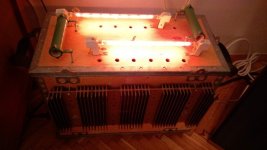
Speaking of an F2 and CCS.. I had gone the other way, I just put the lamps (1500 W, 220v halogen sticks, back then when I could still find them in a shop). Higher PSU voltage of course. Worked wonderfully with my Visaton B200 s on Open Baffle.
And that was a mosfet one, as I never got to upgrade it to F2J...
Just my
And that was a mosfet one, as I never got to upgrade it to F2J...
Just my
Attachments
Thank you for your kind words.You and the others of this forum that are able to undertake such explorations have my respect and gratitude.
To be honest, my knowledge is quite limited, there are many people here on the forum who are true electronics experts, while I’m just scratching the surface.
I wanted to share some results from my LTSpice simulation. I ran a square wave test under identical conditions for both CCS implementations. The bias current is set to 2.5A, and the voltage between the VAS and CCS is right in the middle at 12V. Both circuits are driven by a 1kHz square wave at 0.2Vpp, and the load is a reactive 200uH / 8Ohms coil, intended to represent a more realistic speaker load (it's not, but it's not as easy to drive as just 8 Ohms resistor).
From the simulation, you can see that the original CCS shows signs of high frequency oscillation under these conditions, while the opto-coupler CCS shows just a single overshoot that quickly settles (like a damped pendulum).
The signal source has a 100 Ohms output impedance.
Of course, this is just simulation data, and it might not reflect real-world behaviour or implementation.
Last edited:
And here’s another example using a load with higher inductance: 500 uH and 8 Ohms. To clarify: this shows the current flowing through the speaker's coil.

Oki doki then! I managed to eliminate the oscillations by adding an extra resistor in parallel with the coil (reducing the output impedance). For the Opto-CCS, 240 Ohm was enough, but for the original one, I had to go down to 51 Ohm
Could this improve high-frequency stability or sonics with complex speaker loads? (In my case, the field coil itself is also powered by a CCS - so I may have two CCS circuits “fighting” each other)
FC PSU is having nothing with amp PSSU and operation, except if you made it as in Yore, where FC was part of amp PSU (acting as DC choke)...... but I reckon you didn't do that
why you put 200uH choke at output?
Why did I add the 200u choke?
To test the amplifier’s output current response at the voice coil. This is important because a current-source amplifier struggles to maintain current proportional to the input voltage when the load isn’t purely resistive, unlike a resistor, a real speaker is a complex load.
Regarding the field coil FC PSU:
FC PSU in my case is also CCS. The field coil and voice coil are somewhat analogous to two windings of a transformer. The FC PSU responds to current changes iinduced from the voice coil by EMF, attempting to keep the field coil current steady. At the same time, the voice coil might react to any fluctuations in the field coil. This interaction could make the speaker a "difficult load" for the F2 amp, which is what I was referring to.
The main question:
Could we actually benefit from using an opto-coupler CCS in the F2?
FC PSU ......... main idea of )good= one is to present better magnetic ensemble than with permanent magnet ...... Mighty Moi being faaaaaaaar from expert there, frankly being as moth to candle, as with many other wakoo things
optocoupler, yeah, handy
will sketch later what I'm sorta thinking right now
but, don't expect CCS with opto being better CCS, startup behavior probably being better but sonics, when CCS is good enough, it is good enough, no matter how it's made
optocoupler, yeah, handy
will sketch later what I'm sorta thinking right now
but, don't expect CCS with opto being better CCS, startup behavior probably being better but sonics, when CCS is good enough, it is good enough, no matter how it's made
What I like about field coils is that, with a variable PSU, I can tune the magnetic flux and find a sweet spot, something that’s just not possible with permanent magnets 🙂FC PSU ......... main idea of )good= one is to present better magnetic ensemble than with permanent magnet ...... Mighty Moi being faaaaaaaar from expert there, frankly being as moth to candle, as with many other wakoo things
awesome, can't wait to see that!optocoupler, yeah, handy
will sketch later what I'm sorta thinking right now
hmmm ok ok 🙂but, don't expect CCS with opto being better CCS, startup behavior probably being better but sonics, when CCS is good enough, it is good enough, no matter how it's made


Babelfish
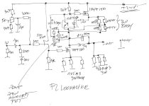
naah, just lookalike
Attachments
thanks for that ZMnaah, just lookalike
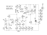
however... I’m not sure this still is a true current source amplifier. In the original F2, the current source behaviour was achieved through DC operating point feedback, but it looks like that feedback mechanism is missing here? I could be wrong, of course 🙂
In the original F2, the current source behaviour was achieved through DC operating point feedback,
I can't see that in files I have
Attachments
- Home
- Amplifiers
- Pass Labs
- DIY F2 clone