@florian911
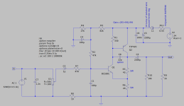
Here is my 3 transistor headphone design in Class A.
This version will suit both 250R and 600R headphones.
The picture shows 10mW (+20dB) into 250 Ohm.
The distortion is only THD 0.00054%
My 3 transistor project has been built by several members with good result.

Here is my 3 transistor headphone design in Class A.
This version will suit both 250R and 600R headphones.
The picture shows 10mW (+20dB) into 250 Ohm.
The distortion is only THD 0.00054%
My 3 transistor project has been built by several members with good result.

I took a quick look at that player. I would not be surprised the output power and sound of that player and that of the 'AAS' amplifier is not a fair comparison. I think the amplifier will blow your ears off, sound-wise and power-wise. Even with those Audeze headphones.my fiio M11 I'm not able to make them sing
What is the role of R8?Like this?
View attachment 1341219
I noticed using 16 ohm headphones with a supply voltage of 19V the 3rd harmonic was bigger than the 2nd one. Increasing the supply voltage to 24V corrected that:
View attachment 1341228
R8 (with R5 and R10 pot) along with R7 set the bias voltage applied to the base of Q1.
Q1 has to be bias accurately to place the emitter of the BD139 close to half Vcc to maximise the headroom from the HPA.
Actually you could bias the voltage at the emitter of BD139 about four volts higher than half Vcc, ie 16V as you have lots of supply voltage..
With 44.5mA running through R3, the voltage at this point is 3.026V, and at the base of Q1 it would be 3.646V.
this is quite a good circuit from Lineout, but you could improve the linearity by replacing the R4 1k by a 12mA constant current source. He added a nice 22pF on Q2, but I would also suggest a 47R base stopper on the BD139.
The bias point should be set higher than half Vcc because the compound 3 transistor amp runs out of puff on the negative rather than the positive half cycle.
You also find that the harmonic profile varies slightly depending on the bias point, as you'd expect.
Hugh
Or save yourself some money and a lot of time and look for a second-hand Schiit Audio Asgard 2;Hello,
I am looking forward to build a headphone amplifier and looking for a project/schematic I could use as a reference. I am looking for the following:
For me its okay to do the PCB layout by myself/use SMD components to shrink the needed size a bit (and accept maybe a bit less performance)
- capable of driving a pair of Beyerdynamic DT880 250 Ohm which I am using at the moment (if possible also the 600Ohm version), probably will upgrade later
- Class A (the single ended class a topology or in genereal the designs by Nelson Pass really appeal to me 🙂 )
- external PSU prefered
- parts which are available at the known large distributors, if possible also in a few years
- maximum size around 200x200x50mm
At the moment I have seen:
Shipping for kits is really expensive, so a bit more DIY would be less expensive (and more fun😉)
- ACP+ (needs to be modified for 250Ohm impedance)
- AMB M³ ("active ground technology" which is new for me)
- Whammy (internal PSU, therefore quite large)
Do you have any recommendations?
Thank you!
Best
Florian
Single-ended Class A MOSFET, zero NFB. Drives my 250-ohm DT 1990 Pro headphones beyond loud.
https://www.schiit.com/public/upload/PDF/asgard_2_owners_manual_1_3.pdf
Is it that time again, for a fresh design?
I made an HPA a couple of years ago for the DT880, but I wouldn't recommend it. Like others have suggested, the Noir could be a good place to start. Me being me, though, I like to go through the process and evaluate all the important details.
I made an HPA a couple of years ago for the DT880, but I wouldn't recommend it. Like others have suggested, the Noir could be a good place to start. Me being me, though, I like to go through the process and evaluate all the important details.
Hugh, was not asking about Lineup circuit but the one in #66. That's why i quoted it in my question.R8 (with R5 and R10 pot) along with R7 set the bias voltage applied to the base of Q1.
Q1 has to be bias accurately to place the emitter of the BD139 close to half Vcc to maximise the headroom from the HPA.
Actually you could bias the voltage at the emitter of BD139 about four volts higher than half Vcc, ie 16V as you have lots of supply voltage..
With 44.5mA running through R3, the voltage at this point is 3.026V, and at the base of Q1 it would be 3.646V.
this is quite a good circuit from Lineout, but you could improve the linearity by replacing the R4 1k by a 12mA constant current source. He added a nice 22pF on Q2, but I would also suggest a 47R base stopper on the BD139.
The bias point should be set higher than half Vcc because the compound 3 transistor amp runs out of puff on the negative rather than the positive half cycle.
You also find that the harmonic profile varies slightly depending on the bias point, as you'd expect.
Hugh
You also find that the harmonic profile varies slightly depending on the bias point, as you'd expect.
Hugh
Perhaps a brain fart: what about developing this beauty in a little monster, doing a bridged version of it so that it can run balanced (and possibly with a bal/un switch)?Is it that time again, for a fresh design?
I made an HPA a couple of years ago for the DT880, but I wouldn't recommend it. Like others have suggested, the Noir could be a good place to start. Me being me, though, I like to go through the process and evaluate all the important details.
Same PSU but with a virtual ground. yes, bulkier than a cigarette box but... (don't know, I'm thinking aloud)
@abstract DT880 what impedance?
I got all the parts in this circuit and could put it together in half a day. (even i have way too many headphone amps already)
Because of C2 cap, R8 does nothing for bias of Q1. That i understand. I was just asking for its function, as i normally would omit it.
How big heatsink on Q2?
Because of C2 cap, R8 does nothing for bias of Q1. That i understand. I was just asking for its function, as i normally would omit it.
How big heatsink on Q2?
Attachments
Ah, my mistake......
It is a ground lifting resistor, intended to cover any earth loops which might drive current into the ground of the input circuit.
As configured, it would run almost 315mA through Q2, and I consider this absurd for a >32R can. Given the efficiciency of cans, say around 93dB at the ear from 1mW, 32R cans would use about 4Vpp, needing a max current of only 62mA for ear splitting Spl. I would set it no higher than 53mA, so use resistors of 120R (for 20R) and 270R (for 43R). No change to the biasing resistors, and I have allowed about one volt drop across the bias resistor, R2 of 47k. At this output current, Q2 will be dissipating 725mW so it needs a flag heatsink. You might also experiment with R4; I'd reckon reducing it to about 22k to bring down the collector of Q3 to around 14.5V, best for headroom but slightly less current to 37mA.
HD
Last edited:

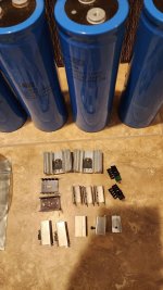
I will be using some of these scrap heatsinks for Q2. If i decide to go with high power version (20R + 43R) i will use those on top, or if lower power (120R + 270R) or between, than something smaller will suffice.
This will be based on all leftover parts, just like was my hamptone project. Still can yield interesting stuff. Nothing goes to waste.
But i have some fm active antena on the 'bench' first. I do not have bench, haha.
Ps: do not worry about those transistors on heatsinks, those are some leftovers from salvage, i will use new transistors, i have plenty.
Attachments
That's exactly what I'll be doing... Hey, if you don't mind, share you notes for the FM antenna! Is it indoor?I will be using some of these scrap heatsinks for Q2. If i decide to go with high power version (20R + 43R) i will use those on top, or if lower power (120R + 270R) or between, than something smaller will suffice.
This will be based on all leftover parts, just like was my hamptone project. Still can yield interesting stuff. Nothing goes to waste.
But i have some fm active antena on the 'bench' first. I do not have bench, haha.
Ps: do not worry about those transistors on heatsinks, those are some leftovers from salvage, i will use new transistors, i have plenty.
Too many components, I'll let starve my family 😁😁😁View attachment 1341773
Been there done that, works like a dream
250 ohm.DT880 what impedance?
If I get a moment I should sketch something up.
How about something modular, like a single-ended MOSFET + switchable
resistor / CCS / choke? I could see myself doing lots of listening experiments or maybe changing the settings depending on mood or music genre.
Sure, but its out of the scope of this thread. Its indoors or outdoors. Highly tunable, not only frequency to amplify, but gain as well. Its tree LC circuits with feedback. Pretty tricky to set properly, but once working, you get high gain with high selectivity. You can place the dipole into directional antena and gain multilies. Crazy. I used it in europe in old commies czechoslovakia to listen western fm stations in perfect stereo from hundreds of miles away. Just a teazer.That's exactly what I'll be doing... Hey, if you don't mind, share you notes for the FM antenna! Is it indoor?
Attachments
Last edited by a moderator:
- Home
- Amplifiers
- Headphone Systems
- DIY Class A Headphone Amp suggestion