So the normal gain is 28 dB which equates to approximately 27.3xI don't want to go through all 274 pages, maybe it's already been mentioned here, what is the input sensitivity of the Wolverine V5 for full output?
Thanks 🙂
So.....
For a version with approximately +/- 50Vdc rails you need 1.3 Vrms for maximum output.
For a version with approximately +/-71Vdc rails
You need approximately 1.8 Vrms for full output.
You can also choose if you would like 27k Ohm input impedance or 10 kOhm input impedance.
For normal modern sources with 2Vrms output it represents an easy load to drive.
Hope this helps
- Dan

Ok guys a bit of news today.....
After alot work from the Wolverine team
I have in my hands the V5 EF3-5 pair
Mirrored boards and parts in my hands.
Special thanks to Stuart for his extra efforts to make the mirrored boards a reality.

Time to start building!
- Dan
After alot work from the Wolverine team
I have in my hands the V5 EF3-5 pair
Mirrored boards and parts in my hands.
Special thanks to Stuart for his extra efforts to make the mirrored boards a reality.
Time to start building!
- Dan
Amazing work guys, looking forward to getting these new boards.
When selecting parts for my Wolverine-EF3 project, I found that the BOM proposes for power supply capacitors among others KEMET type ALC10S1103DH for for max 63V voltage. It is one of the few audio grade capacitors. According to the specification they have patented "slit foil" construction designed specifically for audio applications. In addition to that, only few essential characteristics are specified, i.e. long life, up to 18,000 hours at +85°C and leakage current I = 0.006 CV (= 3.78 mA @ 63 V). I am aware that power supply capacitors are essential for amplifier performance and their price is a remarkable part of amplifier costs.
I am now wondering what are the advantages of this audio grade type compared for example to KEMET type ALC70A103CF063, when the only specified differences are the slit foil construction and a somewhat shorter (but sufficient) lifetime of 13 000 hours. The specification states that the patented slit foil design eliminates circulating currents in the aluminium foils. This is totally new thing for me and I have no idea what would be the advantage of this feature. Could somebody explain? Has anybody measured any difference between the characteristics of slit foil and ordinary capacitors? If there are some differences in addition to the slightly longer lifetime, do you consider it wise to pay their 40 % higher price or invest 40 % more in ordinary capacitors?
Martant
Attachments
Power supply capacitors are good or not on their own. I guess you could argue that high frequency design might be better, but you really ought to have local bypass caps. So it comes down to quality. I think the term audio grade is more marketing than anything.
Hi Guys,
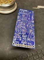
I am ready for the initial test without the output transistors installed. I am working with the EF3-4 (V. 4.0) boards. I've installed a 9.1K resistor in parallel with R17, J-103 jumper wire is in place, input is shorted, R25 and R11 are set to the midpoint of their ranges, and R109 is maxed out.
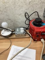
Question: I'm using the recommended 0.5 A fuses, but they are fast blo, not slow blo. Is this ok? I'll be using a bench power supply of +/-30V clamped at 0.3A
Thanks,
John
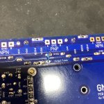
PS: I love the look of these boards.....its profile looks like a city landscape. If I survive this build, I may have to take a crack at those newly released boards; they do look delicious!
I am ready for the initial test without the output transistors installed. I am working with the EF3-4 (V. 4.0) boards. I've installed a 9.1K resistor in parallel with R17, J-103 jumper wire is in place, input is shorted, R25 and R11 are set to the midpoint of their ranges, and R109 is maxed out.
Question: I'm using the recommended 0.5 A fuses, but they are fast blo, not slow blo. Is this ok? I'll be using a bench power supply of +/-30V clamped at 0.3A
Thanks,
John
PS: I love the look of these boards.....its profile looks like a city landscape. If I survive this build, I may have to take a crack at those newly released boards; they do look delicious!
Attachments

All good on 0.5A fast blow - if you have the ability to bring the rails up slowly, maintaining the current limit 200-300mA, rather than just dumping on a current limited 30V please do so. You will see any "issues" (excessive current draw) around first around 1.5V-2V, then again around 7-10V, then you should be okay to 30V and onto full rails.
your SIP1 header looks installed upside down possibly, did you have any side on photos of the IPS
anatech,
I really appreciate your realistic view about capacitors based on facts and experience in audio area. Being an electrical engineer, it helps me to make my selections on healthy grounds based on adequate published and measurable characteristics. Thank you very much!
Martant
I really appreciate your realistic view about capacitors based on facts and experience in audio area. Being an electrical engineer, it helps me to make my selections on healthy grounds based on adequate published and measurable characteristics. Thank you very much!
Martant
Just reaffirm your male SIP header is correct or you may have a host of issues see this pic, the smaller slimmer pins are the solder side and the longer round pins are to connect to the femaleHi Guys,
I am ready for the initial test without the output transistors installed. I am working with the EF3-4 (V. 4.0) boards. I've installed a 9.1K resistor in parallel with R17, J-103 jumper wire is in place, input is shorted, R25 and R11 are set to the midpoint of their ranges, and R109 is maxed out.
Question: I'm using the recommended 0.5 A fuses, but they are fast blo, not slow blo. Is this ok? I'll be using a bench power supply of +/-30V clamped at 0.3A
Thanks,
John
PS: I love the look of these boards.....its profile looks like a city landscape. If I survive this build, I may have to take a crack at those newly released boards; they do look delicious!
.
The only way I know to do this is to go back to my dim bulb/variable transformer set-up. Is that what I should do....and then switch to the bench power supply when I don't see smoke?All good on 0.5A fast blow - if you have the ability to bring the rails up slowly, maintaining the current limit 200-300mA, rather than just dumping on a current limited 30V please do so. You will see any "issues" (excessive current draw) around first around 1.5V-2V, then again around 7-10V, then you should be okay to 30V and onto full rails.
See picture of IPS board: do I have those pins right? They seem to fit like a glove.
Attachments
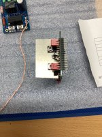
Ok, I have apparently flipped both 14 pin headers out of sheer ignorance. I tried to remove one with a Hakko De-soldering gun and some flux. It won't let go. Getting more physical will destroy the board. The male and female header seem to fit together well, that is, it's not loose. I did ohm out each of the pins, and I have a good connection. Unless someone has a better suggestion for removal, I am going to leave them as they are.😒
Before you used the desoldering tool did you warm the board up First?
I find if I'm doing any desoldering of a few components, I whip it in my oven at about 40 or a little higher degrees for around 10 minutes and flux top and bottom and then desoldering. Braid comes in handy too.
Tony
I find if I'm doing any desoldering of a few components, I whip it in my oven at about 40 or a little higher degrees for around 10 minutes and flux top and bottom and then desoldering. Braid comes in handy too.
Tony
Consider ChipQuik desoldering alloy if you have it or can order it. There are various videos online detailing its use.Ok, I have apparently flipped both 14 pin headers out of sheer ignorance. I tried to remove one with a Hakko De-soldering gun and some flux. It won't let go. Getting more physical will destroy the board. The male and female header seem to fit together well, that is, it's not loose. I did ohm out each of the pins, and I have a good connection. Unless someone has a better suggestion for removal, I am going to leave them as they are.😒
Don't want to destroy your pcb though so be careful.
Best,
Anand.
No, I didn't warm the board, but I did follow up with flux and braid. That thing will not budge.Before you used the desoldering tool did you warm the board up First?
I find if I'm doing any desoldering of a few components, I whip it in my oven at about 40 or a little higher degrees for around 10 minutes and flux top and bottom and then desoldering. Braid comes in handy too.
Tony
Thanks for the suggestion,
John
Mr. Solderfix is brilliant! I'm going to try it.
Thanks dovia83!
John
Thanks dovia83!
John
- Home
- Amplifiers
- Solid State
- DIY Class A/B Amp The "Wolverine" build thread