Ah I see you have started with an older BOM. The bias circuit was redesigned. The old one still works but the redesign is much better.
Again, I strongly advise you review, replace as necessary, and populate your boards to the latest:
1st GB BOM - May 2024 spreadsheet
Also make sure you review the latest build guide - and apply the correct updated changes to Q103 and 104.
Do not mix and match parts from BOMs that have the earlier bias parts with BOMs that have the revised bias parts. I’ll link to the post where that change was made.
https://www.diyaudio.com/community/...he-wolverine-build-thread.385920/post-7360185
BOMs and build guides pre may 2023 will have the original resistor and Q103/104 parts
BOMs and build guides may 2023 and onward will have the “revised” parts.
Last edited:

Yes, I started with older BOM. I have just compared resistor values I used with BOM May 2024 and it looks that my EF3-3 is OK (perpendicular to main heatsink pcb mounting), while in my EF3-4 I used resistor values for driver mounting on the main heatsink as BOM I used did not differentiate between main heatsink and perpendicular driver mounting on 3mm separate heatsinks. Theoretically I could mount my EF3-4 pcbs on the main heatsinks but I prefer perpendicular mounting so I have to change 3 or 4 resistor values. Hopefully I'll manage it without damaging pcbs. Alternatively I can solder additional resistors in parallel as resistors I used have higher resistances.Ah I see you have started with an older BOM. The bias circuit was redesigned. The old one still works but the redesign is much better.
Again, I strongly advise you review, replace as necessary, and populate your boards to the latest:
1st GB BOM - May 2024 spreadsheet
Also make sure you review the latest build guide - and apply the correct updated changes to Q103 and 104.
Do not mix and match parts from BOMs that have the earlier bias parts with BOMs that have the revised bias parts. I’ll link to the post where that change was made.
https://www.diyaudio.com/community/...he-wolverine-build-thread.385920/post-7360185
BOMs and build guides pre may 2023 will have the original resistor and Q103/104 parts
BOMs and build guides may 2023 and onward will have the “revised” parts.
Yes, I have noticed that mounting of Q103 and Q104 has been changed.
If you worried about this just cut the resistor legs off from the body of the resistor then you can just heat up and pull the single piece of wire out from the pad.Hopefully I'll manage it without damaging pcbs
Hello there,
I'm new to this "Wolverine" thread ...
So much reading to do.
Could somebody 'link' me to the Output Stage schematic diagram?
Cheers all 🙂
I'm new to this "Wolverine" thread ...
So much reading to do.
Could somebody 'link' me to the Output Stage schematic diagram?
Cheers all 🙂
Resistors are the easiest parts to pull out but if I encounter problems I'll follow your advice.If you worried about this just cut the resistor legs off from the body of the resistor then you can just heat up and pull the single piece of wire out from the pad.
Please read the first post.Hello there,
I'm new to this "Wolverine" thread ...
So much reading to do.
Could somebody 'link' me to the Output Stage schematic diagram?
Cheers all 🙂
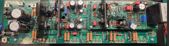
I made some progress during the holidays - IPS finished and tested, EF3-4 boards almost finished.


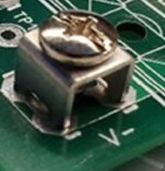
Still figuring out the best solution for mounting the pre drivers to the heatsink, the nut inferferes with the adjuster on the trimmpot. Buttonhead would work but then I won't be able to unscrew the transistor if I have to change it someday.


Power supply layout:

I like this project a lot 😁
Still figuring out the best solution for mounting the pre drivers to the heatsink, the nut inferferes with the adjuster on the trimmpot. Buttonhead would work but then I won't be able to unscrew the transistor if I have to change it someday.
Power supply layout:
I like this project a lot 😁
Thanks for the feedback David. I'll look into raising the pre drivers up a little so you can remove that button head cap screw.Buttonhead would work but then I won't be able to unscrew the transistor if I have to change it someday.
I have my initial readings from the left channel and some issues. I used 30DCV and 0.3 amps for power from the DCV regulated supply.
The two Leds on the IPS don't light up.
Otherwise, my readings are within target.
I checked the LED orientation.
Is the LED issue because I've restricted DCV to 30V?
The two Leds on the IPS don't light up.
Otherwise, my readings are within target.
I checked the LED orientation.
Is the LED issue because I've restricted DCV to 30V?
Attachments
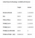
Due to the low voltage did you place the temporary 9.1K resistor in parallel with R17?I used 30DCV
If you didn't, do that, and that should solve your leds not lighting up.
It's in the notes of the build guide at point 15.1Duh! Hitting my head against the wall.
Wow, I've looked all over, can't find the hitting the head part in the notes!
Just to be clear I was talking about the 9.1K resistor. Although I think @RickRay was making a joke.... 😁😅🤣😅😁Wow, I've looked all over, can't find the hitting the head part in the notes!
- Home
- Amplifiers
- Solid State
- DIY Class A/B Amp The "Wolverine" build thread