If you drill and tap holes in your heatsink, you will need some lubricant to cut the threads. Good point about cleaning those holes.

2nd round of testing/biasing:
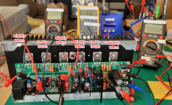
I achieved initial power up. [DC power supply set at 30DCV 0.3A]
I installed output transistors [DC power supply set at 30DCV 3.0A]
After 45 minutes the bias is wavering between 43.0 and 44mV. Note I don't have the amp sink installed in case and covered.
I did notice that the six transistors varied in temperature. I assume [hope] that is because I'm only using 30DCV and 1A to power the board.
Assuming nothing is amiss tomorrow I will insert the board in the case and using full power hopefully achieve bias target of 40 to 45 DCV mV .
Attachments
Maybe I need a vacation.
I tested thru initial testing A-ok.
I proceeded to output transistor testing. Very early in biasing the bias started to cycle wildly and then the fuses blew.
I'm hoping this was caused by my forgetting to remove R17 and J-103.
Is that a fair hope? I've tested all the resistors, and nothing looks blown.
Perhaps you could invest in infrared thermometer. Just to be sure and accurate. There are some limitations when measuring very close objects or shiny surfaces, but in general its preffered method.
https://www.google.com/search?q=ir+...d-att-us-rvc3&sourceid=chrome-mobile&ie=UTF-8
https://www.google.com/search?q=ir+...d-att-us-rvc3&sourceid=chrome-mobile&ie=UTF-8
Have I had a stroke?
I cannot figure out where or how to buy these boards,
Or if any are left.
Maybe this is what they actually mean when they speak the phrase "senior discount."
I cannot figure out where or how to buy these boards,
Or if any are left.
Maybe this is what they actually mean when they speak the phrase "senior discount."
Go to the Group Buy thread https://www.diyaudio.com/community/threads/the-wolverine-4th-group-buy.411286/
Assuming you mean the parallel resistor you add to R17 for testing, and didnt completely remove R17,I'm hoping this was caused by my forgetting to remove R17 and J-103.
Yes, leaving the temp R17 parallel resistor, and J103 in with output transistors would probably cause all manner of chaos!
Hi guys,
Today I received 16 AWG (1.4mm diameter) coated magnet wire from Remington Industries here in the States. Using a 12mm steel bar I attempted my first coil winding.
It can only be described as "ugly". In his video how did Daniel wind that coil so tightly and evenly. I know he used epoxy, but that was after he did the winding. Is there a trick to doing this neatly.
Any help would be appreciated,
John
I hooked up the amp board to the DC power supply at 30DCV and 3A.Maybe I need a vacation.
I tested thru initial testing A-ok.
I proceeded to output transistor testing. Very early in biasing the bias started to cycle wildly and then the fuses blew.
I'm hoping this was caused by my forgetting to remove R17 and J-103.
Is that a fair hope? I've tested all the resistors, and nothing looks blown.
I removed R17 and J-103.
Nada. No LED lights.
I don't see any burnt parts.
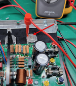
When I check for shorts from the output transistors to the heat sink, from the flat washer to the black heat sink I get a reading of OL across all of them.
When testing from the transistor washer to the silver-colored mounting bracket on the heat sink I get a range of 1.4R to 1.6R. These results are confusing.
I retested 19. B. My readings don't look right for IV and V as all results need to exceed 10K ohms:
I. -66.4K
II. 61.3K
III. 70.1K
IV. 0.5R
V. 1.7R
Any thoughts on what my situation is at this point would be appreciated.
Attachments
IV and V - Still blown outputs and/or perhaps blown drivers. At this point you may need to enlist the help of a local diya member, as its difficult within the forum to diagnose and repair.
You have one good amp board or is this both?
You have one good amp board or is this both?
Lathes - who needs lathes 😉?Hi guys,
Today I received 16 AWG (1.4mm diameter) coated magnet wire from Remington Industries here in the States. Using a 12mm steel bar I attempted my first coil winding.
It can only be described as "ugly". In his video how did Daniel wind that coil so tightly and evenly. I know he used epoxy, but that was after he did the winding. Is there a trick to doing this neatly.
Any help would be appreciated,
John
The way I did it was crude, but it worked pretty well. I call this the "handheld wobbly lathe". Using an old speaker crossover inductor as my wire, I slid one end of the wire into the chuck of a cordless drill alongside a 12mm (new, not rusty) drill bit and clamped the chuck down so one of the chuck teeth clamped the wire. You need the drill bit sitting quite a way out of the chuck, so you get "clean" former and don't run up into the cutting spirals. The drill bit sits crooked, but this is no concern. I wound out some wire and held the remainder in other hand and began to slowly, whilst holding the inductor tight to keep the wire under tension, wind the new coil onto the drill bit. You can place the cordless drill in a vice or press it down flat on a bench if you need the extra strength. I wound well past the amount of turns I needed, then keeping the tension on, vice clamped the excess to the end of the drill bit. Cut away the remaining old inductor and apply glue over top of the whole formed coil but don't get glue on the drill bit or you won't get the coil off. When dry, unclamp and unwind the coils you don't need. Slip the coil off the drill bit - back the short way not over the cutting spirals. You will likely fail the first couple attempts, but I got better each time until I got nice, neat tight coils. Now I have done about 6 ultra neat coils. If you use an old drill bit you also wont get the coil off the drill bit.
Its stupid, but it work.
Last edited:
You can also check individual components.I have one of those. You mean for reading the temperature of the heat sink?
Time to start from scratch again. Remove the outputs. Start with testing the Input board seperatly, then move on to testing output board without the outputs, etc. Slow down and make a checklist and follow it.I hooked up the amp board to the DC power supply at 30DCV and 3A.
I removed R17 and J-103.
Nada. No LED lights.
I don't see any burnt parts.
When I check for shorts from the output transistors to the heat sink, from the flat washer to the black heat sink I get a reading of OL across all of them.
When testing from the transistor washer to the silver-colored mounting bracket on the heat sink I get a range of 1.4R to 1.6R. These results are confusing.
I retested 19. B. My readings don't look right for IV and V as all results need to exceed 10K ohms:
I. -66.4K
II. 61.3K
III. 70.1K
IV. 0.5R
V. 1.7R
Any thoughts on what my situation is at this point would be appreciated.
This is the first board I've built. I can at least remove and test the outputs. I guess I could remove the drivers and test them too. Beyond that it probably makes more sense to build a fresh board and hope to learn from my past experience.IV and V - Still blown outputs and/or perhaps blown drivers. At this point you may need to enlist the help of a local diya member, as its difficult within the forum to diagnose and repair.
You have one good amp board or is this both?
I agree with RickRay - my first step would be to start easy - which is test the input board - exactly how the build guide illustrates. Then you mark that off the list as good. Hopefully its a solder bridge or mismatched/blown resistor or diode. Unlikely, since you got all LEDs to light in previous testing.
Then test each output, driver, pre-driver, basically anything you can get to with a DMM (in circuit BCE - thankfully the Wolverine team marked legs on the top and bottom of the board) - this will tell you if you have any gross shorts on these transistors. If that does not provide any insight, the next step is to methodically remove and test out of circuit moving backwards to each amp section (outputs, drivers, pre-drivers, etc.) following the schematic and marking as good (green check mark), or bad (red X), until you test an entire section and have no faultily transistors.
Then the fun part - test resistors/diodes around any faulty transistors you find, but these can be done in circuit. Again, marking everything on your schematic for easy upload to this thread, or if you enlist the help of a member close by - you have somewhere to start the assisted diagnosis. You might get lucky and it's a low value resistor that has gone high value from your previous issue, but this sounds like another transistor blew from your previous issue, you just haven't found it yet.
Once you have "found" any bad parts and replaced them - do your methodical bench testing, going slow and marking off each step in the build guide along the way. Working your way back to a fully populated amp channel and testing with the DMM. If that checks out, then use a DBT, or Variac to bring it up slowly watching the current draw, so have a quick hand on the power switch at all times.
- Home
- Amplifiers
- Solid State
- DIY Class A/B Amp The "Wolverine" build thread