Finally found both product numbers:
Thermalcote™: 250G Thermalcote is a superior silicone-based thermal joint compound uniquely developed to increase heat transfer to all heat sinks. Thermalcote’s thermal conductivity is more than 15 times that of air and more than 4 times the conductivity of typical silicone-based greases. It is non-toxic and extremely stable; it neither cakes nor runs between -40°C to 204°C. 250G is a 57 gram (2 oz.) tube of Thermalcote. Representative image only.
The WAKEFIELD part 120-2 is a highly efficient thermal management solution designed to ensure optimum heat dissipation in electronic systems. This temperature-resistant thermal grease boasts excellent thermal conductivity, with a 56°C/W thermal resistance and a thermal conductivity of 0.735W/m.K. Its opaque white composition allows for easy visibility during application, ensuring precise and uniform distribution of the grease. The thermal grease is supplied in a convenient jar, making it easy to access and apply.With a high electrical resistance of 5X10e14 Ohm.cm, this thermal grease provides excellent electrical insulation properties, ensuring the safety and reliability of your electronic components.Whether you're working on a DIY project or maintaining professional electronic systems, the WAKEFIELD part 120-2 is the ideal thermal management solution to keep your devices cool and running efficiently.
Looks like what I used, Thermalcote and what I intend to use are both conductive.

You don't need to lather on thermal pastes. Just enough to spread thinly and fill the microscopic imperfections between the two surfaces to which its being applied. Too much eventually becomes inefficient.
Less is more. Got it. Thanks.
Just dip a fine paintbrush into the thermal paste then spread it very thinly just enough to cover the surface (just) if it oozes out to much after you tighten the m3 screws you've used to much
Attachments
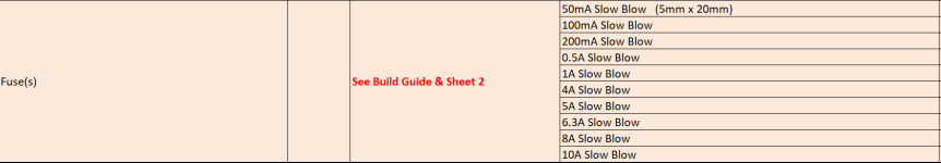
If it were the fuses that were the issue, you wouldn't have lost 2x outputs, you'd have just lost a fuse. The fuse did its job, the Cobra (hopefully), with its fast protection, should have saved anything else.
Of course! I have uploaded them to a GitHub repository: link.
Under 3d-models you will find the bridge and IEC cable mount models. I regret not having made them a bit prettier now, but oh well 🙂
@Ponti17. If you zip up the 3D files (STL, 3MF, CAD file, etc...) you can post them in the thread directly for easy download. Always fun to see custom 3D print designs used in diyaudio.
Nice work and thanks for sharing!
Just confirming I will use slow blow fuses as listed in the BOM. Thanks.If it were the fuses that were the issue, you wouldn't have lost 2x outputs, you'd have just lost a fuse. The fuse did its job, the Cobra (hopefully), with its fast protection, should have saved anything else.
Last edited:
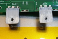
mainframe, somehow I remember reading this and what really stuck with me was "burr." Glad I remembered. This is exactly what my experience was that also resulted in crashing bias and 2 transistors and 4 resistors getting blown.While we're on heat transfer and the Q103 topic, Here's my **** up on my latest EF3-4 build (currently have an EF3-3 build working fine) for others to look out for:
I got through all the testing stages with no outputs installed fine, Using a bench variac on a quick single bridge and 2x smoothing caps DC supply for testing up to 70VDC
1. I then installed the outputs and the assembly onto the heatsink - Keep in mind my Q103 location - it was as per the latest build guide in the preferred location which is between the drivers (which are also) on the main heatsink, in the tri-arrangement under the PCB, mounted parallel with the main heatsink. Exactly as @danieljw had pictured on the previous page in other words. My heatsinks were bare so I drilled and tapped all the output, standoff and driver/q103 holes myself
2. I installed 2A fuses to begin the next round of testing, and all tests passed. However my first mistake was not letting the amp sit for long enough here with the bias turned up to spec. I checked it got to spec and then wound it back down to proceed to the next step
The next 3 steps happened fast so keep in mind;
3. I installed 8A fuses and began final biasing. Watching the bias voltage like a hawk, I noticed it got up to spec after turning R109 up a bit, and then after 5 2-3 minutes (all while slowly turning the R109 back down as the amp warms up) started to slowly drop, which I thought is not normal. I suddenly tried winding R109 up to counter it. Little did I know the heatsinks and outputs were getting hot at this point.
4. The bias voltage plummeted - I didn't realize at the time it was (I think) Q103 finally getting some heat and trying to crash the bias but it was too late.
5. An 8 amp rail fuse blew, I immediately A-Z5'd the amp. 2 of the outputs were extremely hot, Later found I lost 2x PNP outputs.
6. I checked the other channel - observed similar behavior, but this time with current meters on the rails I managed to shut off the amp when the current started to peg (normally about 350-400mA per channel idle I believe), this was shooting up toward 1 amp (as high as the meter goes) before I shut it down and felt the heatsink, also extremely hot.
7. Spent a day checking my work thinking I had a component in backwards somewhere or a resistor off by a factor of 10 or something
8. My face when I realize the one hole, on both heatsinks, that I had forgotten to debur after tapping, was for Q103. So even though Q103 had thermal paste on it, it wasn't screwing down flush to the heatsink. It would have been 0.2-0.4mm proud of the heatsink. Thermal runaway, (me being cheap and using boron in the control rods jk/not being thorough enough)
There you have it folks, dont be like me, check all your heatsink holes are clean, and free of burrs. All transistors need good flush contact with their heatsinks!
When I run my finger over the holes for the output transistors, I can feel the edge of each hole. When I do the same with holes I haven't screwed into, they are smooth. I assume that is what I want. Any suggestions of what to use to file down or smooth out the edges that I feel?
Thanks for taking the time to report the above. I know I've benefitted, and others will too.
Just take a larger drill bit - say 6 to 7mm or 1/4Inch and put it in the hole you made and spin it with your fingers with a bit of force a few times. If you don’t have the grip strength for this you can do it with a cordless drill, just with very little pressure on the drill instead. The larger drill bits taper will nicely cut the top edge or “file” the hole in a nice circle. Daniel’s videos show this somewhere also…
You must always do this with heatsink applications. I missed it on the one hole only and paid the price.
You must always do this with heatsink applications. I missed it on the one hole only and paid the price.
Beautiful work 👏 👌Wired my Wolverine today and gave it the first listen. And wow, not sure if it's because of all the work that have gone into it, but it sounds really good on my not so fancy speakers. The sound feels very controlled and yet with lots of power (and now i will use no more meaningless audiophile jargon 🙂 ).
It was difficult to finalize on a good wiring scheme, especially since i have no skills whatsoever in working with metal (nor any tools), making it difficult to create new mounting points for wires. I do however have a 3D printer, so i printed some plastic wire "bridges" in ASA plastic. The result might be kind of stupid, but it works pretty well.
My fairly sensitive speakers are nearly dead quiet when the amp is on, except for the faintest buzz when i have my ear pretty much touching the tweeter of the left speaker. I have a feeling it might be due to the sub-optimal placement of the left input wire right next to the output of the right channel. I will have to optimize the wiring a bit before finally putting the top lid on it, but it's difficult to stop the music and unplug it from the wall.
All in all, for those currently building one, you should be very excited to hear it when it's done 🙂
View attachment 1369431
View attachment 1369432
Just adding more to this while we on the topic - If you're use a cutting compound to assist with the drilling or tapping holes (you usually shouldn't need to with aluminum as its soft), this should be cleaned out of the holes otherwise when the transistors are screwed down it will ooze up and get in-between your pad and heatsink and really degrade thermal transfer.Just take a larger drill bit - say 6 to 7mm or 1/4Inch and put it in the hole you made and spin it with your fingers with a bit of force a few times. If you don’t have the grip strength for this you can do it with a cordless drill, just with very little pressure on the drill instead. The larger drill bits taper will nicely cut the top edge or “file” the hole in a nice circle. Daniel’s videos show this somewhere also…
You must always do this with heatsink applications. I missed it on the one hole only and paid the price.
Last edited:
- Home
- Amplifiers
- Solid State
- DIY Class A/B Amp The "Wolverine" build thread