Hi John,
Your correct the edge mount for Q104 is no longer required or recommended to use now that Q104 is the ambient temperature sensor.
Where you currently have Q104 is correct.
Thank you Stuart!
John
@jminassi thanks, it also looks very nice in the dark 🙂
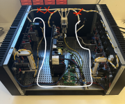
As mentioned in my previous post i really have no skills nor tools for working with metal, so i did not drill it myself. The chassis is bought from Modushop and they offer a fairly priced "drilling" service. You just have to send them the drawings. They are very helpful if you have any questions for them 🙂
As mentioned in my previous post i really have no skills nor tools for working with metal, so i did not drill it myself. The chassis is bought from Modushop and they offer a fairly priced "drilling" service. You just have to send them the drawings. They are very helpful if you have any questions for them 🙂

Amazing work Ponti17, well done. If you don't mind, I have a couple questions for you on your build.
Did you 3D print the wire bridges that go over the boards? They look great.
What cable ties are you using to run wires accross the top of the heatsink, did they require drilling?
Love the photos, thanks for any info!
Did you 3D print the wire bridges that go over the boards? They look great.
What cable ties are you using to run wires accross the top of the heatsink, did they require drilling?
Love the photos, thanks for any info!
@Dolamike Thanks a lot!Amazing work Ponti17, well done. If you don't mind, I have a couple questions for you on your build.
Did you 3D print the wire bridges that go over the boards? They look great.
What cable ties are you using to run wires accross the top of the heatsink, did they require drilling?
Love the photos, thanks for any info!
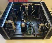
Yes, the white bridges crossing the boards at the output as well as the bridge on top of my IEC inlet are 3D printed 🙂
For running the cables along the boards i use "zip cable mounts" (if that's their official name). They look like this:
You can find them super cheap on AliExpress if you search for something like "zip tie wire mount". They do require drilling (and tapping!) in the heatsinks though. And just to make it clear, using these things in the Wolverine are by no means my original idea. I saw @danieljw's excellent Wolverine build where he uses these 🙂
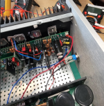
@thimios Thanks for the suggestion! It could be fun to try this instead and see if it removes the very faint buzzing in my left speaker. Though in your suggestion the input wire will run closely past the power supply wires, which might also introduce some noise?Ponti17.
You have done a very good job 👍.
According to Bonsai's wiring guide,here is a better input wires configuration.
Nevertheless i will perhaps try it if i find the time. I'm having a hard time getting an intuition for this stuff so testing different configurations would be good.
Quietest amp I have ever measured or heard connected to a speaker is a Wolverine with a hypex ps500diy powering it. Cant hear a thing. Shame about the power/cooling limitations of that supply.Latte for editing..
I can't imagine an absolutely silent tweeter using smps🤔
(My current Wolverine with linear PSU is almost as good I think only a couple uV higher, only the faintest noise can be heard with ear on the tweeter, late at night)
Hi Nikos,
Hope you are well.
My amps don't have the bias "problem" that you are describing.
This amp has been thoroughly tested by many and it's very stable. We drove Neil and Thimios and JT 😛 crazy getting them to change parts daily so we can come up with the optimum values.
Most likely your amp is different because you are using smaller heatsinks and to compensate you use fans.
Your above setup has not been tested by the design team, so it’s unfair to expect an answer/ solution.
Regards
Harry
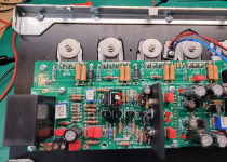
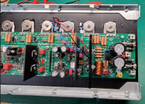
New problem. Yesterday I was in my second day of final bias adjustments for the right channel. after an hour it was holding around 40mV, though it started to dip to 35mV. I looked away and when I looked back the red leds had gone out and a red led trouble light was lit on the Cobra indicating a short at the amp board. The 2AFB V+ fuse was shot.
I have probed with the DMM to find a short on the amp board attached to the heat sink and couldn't find anything. A visual check doesn't show any burned parts that I can see. Over the two days I had the amp on for around 2 hours.
I have been advised not to reattach it to the Cobra until I have found the issue.
I'm thinking of powering it from my DC power supply next.
Any thoughts or ideas would be helpful.
Attachments

Sorry to hear you are having issues.
This sounds eerily similar to the problem I had where I didn't have Q104 contacting the heatsink properly (i.e. truly flat) due to forgetting to debur the hole.
Because I think if you had a fully functioning amp that has failed after two hours, it is much more likely to be a thermal issue. Perhaps too much thermal resistance between the outputs-pads-heatsink-pads-q104. Thermal runaway will generally cause one of the output transistors to overheat to short. Remove the outputs (i used two soldering irons to do this) and check. Its a shame you didn't finger check all the outputs - i bet one or two of them were scorching.
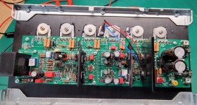
What thermal pads and paste have you used?, you seem to have used excessive amounts. Some thermal compounds are also (counterintuitively) electrically conductive in order to improve thermal transfer. I can see overlaps in the thermal compound from heatsink to outputs.
Some "insulating" pads are just that, they block electrical and heat. Make sure you have silicone thermal insulating pads. Make sure all transistors have nice flush contact with the heatsink and are not overtightened. Make sure no debris have gotten between an output transistor and the heatsink.
I would bet good money an output transistor or two have gone kaput. But that should be the extent of it.
Best of luck.
This raises an eyebrow too

This sounds eerily similar to the problem I had where I didn't have Q104 contacting the heatsink properly (i.e. truly flat) due to forgetting to debur the hole.
Because I think if you had a fully functioning amp that has failed after two hours, it is much more likely to be a thermal issue. Perhaps too much thermal resistance between the outputs-pads-heatsink-pads-q104. Thermal runaway will generally cause one of the output transistors to overheat to short. Remove the outputs (i used two soldering irons to do this) and check. Its a shame you didn't finger check all the outputs - i bet one or two of them were scorching.
What thermal pads and paste have you used?, you seem to have used excessive amounts. Some thermal compounds are also (counterintuitively) electrically conductive in order to improve thermal transfer. I can see overlaps in the thermal compound from heatsink to outputs.
Some "insulating" pads are just that, they block electrical and heat. Make sure you have silicone thermal insulating pads. Make sure all transistors have nice flush contact with the heatsink and are not overtightened. Make sure no debris have gotten between an output transistor and the heatsink.
I would bet good money an output transistor or two have gone kaput. But that should be the extent of it.
Best of luck.
This raises an eyebrow too
Last edited:
Any chance you might be able to share your 3D printer files? I’d love to have some of those bridges printed. 🙂@Dolamike Thanks a lot!
Yes, the white bridges crossing the boards at the output as well as the bridge on top of my IEC inlet are 3D printed 🙂
For running the cables along the boards i use "zip cable mounts" (if that's their official name). They look like this:
View attachment 1369477
You can find them super cheap on AliExpress if you search for something like "zip tie wire mount". They do require drilling (and tapping!) in the heatsinks though. And just to make it clear, using these things in the Wolverine are by no means my original idea. I saw @danieljw's excellent Wolverine build where he uses these 🙂
@thimios Thanks for the suggestion! It could be fun to try this instead and see if it removes the very faint buzzing in my left speaker. Though in your suggestion the input wire will run closely past the power supply wires, which might also introduce some noise?
Nevertheless i will perhaps try it if i find the time. I'm having a hard time getting an intuition for this stuff so testing different configurations would be good.
I’m going to answer my own question here, just in case someone else comes across this. The surface mount pads are on the underside of the board.Hello, I have a question regarding C121, 122, 125, 126. I have the 3-4 4th group buy board. It looks like there are some options here. Any pro's or cons to condider? Does the electrolytic capacitor get installed on top of the surface mount for the preferred option on the BOM? Any info greatly appreciated. Thanks.
View attachment 1369415
Being Fast-Blo and 2A, seems possible it blew from turn on and turn off stress, added to it the bias setting. I use 6A, because I had a 3A fuses self destruct and 4A ones were visibly stressed after a few months, YMMV.New problem. The 2AFB V+ fuse was shot
Hopefully that’s all it is and a new fuse fixes it… but do thorough tests to confirm no shorts and start with the outputs.
Thanks for the info. Sounds about right. I used Mica insulators and Thermalcote I Thermal Joint compound. It doesn't say it is silicone on the label. i also have Wakefield Type 120 Silicone thermal joint compound and I will use that in the next round.Sorry to hear you are having issues.
This sounds eerily similar to the problem I had where I didn't have Q104 contacting the heatsink properly (i.e. truly flat) due to forgetting to debur the hole.
Because I think if you had a fully functioning amp that has failed after two hours, it is much more likely to be a thermal issue. Perhaps too much thermal resistance between the outputs-pads-heatsink-pads-q104. Thermal runaway will generally cause one of the output transistors to overheat to short. Remove the outputs (i used two soldering irons to do this) and check. Its a shame you didn't finger check all the outputs - i bet one or two of them were scorching.
What thermal pads and paste have you used?, you seem to have used excessive amounts. Some thermal compounds are also (counterintuitively) electrically conductive in order to improve thermal transfer. I can see overlaps in the thermal compound from heatsink to outputs.
Some "insulating" pads are just that, they block electrical and heat. Make sure you have silicone thermal insulating pads. Make sure all transistors have nice flush contact with the heatsink and are not overtightened. Make sure no debris have gotten between an output transistor and the heatsink.
I would bet good money an output transistor or two have gone kaput. But that should be the extent of it.
Best of luck.
This raises an eyebrow too
View attachment 1369543
I will demount the outputs and confirm their status.
Should be a nice Saturday project.
I will fix the V+ wire orientation away from the front panel. Good catch.
Hi Guy's,
Just letting you know Jeremy and Neil from the Wolverine Team will be at the Burning Amp Festival tomorrow. I'm sure they'd be happy to chat to any fellow forum members who attend.
I hope they have a great day.
Just letting you know Jeremy and Neil from the Wolverine Team will be at the Burning Amp Festival tomorrow. I'm sure they'd be happy to chat to any fellow forum members who attend.
I hope they have a great day.
What's the part number of the thermal compund you used? Many compunds are electrically conductive and will eventually work their way to somewhere they shouldn't and blow the fuses.Thanks for the info. Sounds about right. I used Mica insulators and Thermalcote I Thermal Joint compound. It doesn't say it is silicone on the label. i also have Wakefield Type 120 Silicone thermal joint compound and I will use that in the next round.
I will demount the outputs and confirm their status.
Should be a nice Saturday project.
I will fix the V+ wire orientation away from the front panel. Good catch.
Of course! I have uploaded them to a GitHub repository: link.Any chance you might be able to share your 3D printer files? I’d love to have some of those bridges printed. 🙂
Under 3d-models you will find the bridge and IEC cable mount models. I regret not having made them a bit prettier now, but oh well 🙂
- Home
- Amplifiers
- Solid State
- DIY Class A/B Amp The "Wolverine" build thread