
Mainframe is right in his suggestions.
The team did alot of work to improve the bias thermal behaviour.
Take your time with this step and incrementally (small steps) adjust until you achieve around 44 mV.
It is best to do this again in the case once completed but you can get it all going on the bench and then re-bias/tweak as needed.
- Dan
Last edited:
Hi mainframe99you're doing great, yep that's normal bias behavior as the outputs heat the heatsink. If bias has already been set at warm idle, The EF3-4 can climb to 65-70mV at cold start up before dropping down to steady 40-44mV
Ιs this operating range (climb to 65-70mV at cold start up before dropping down to steady 40-44mV) you mention stable? for each ambient temperature winter -summer;
Its most drastic range in winter i.e. coldest heatsink so it goes the highest 65-70mV and doesn't go as high in summer because the heatsink is warmer due to warmer ambient. Its not a concern. These are only observations on the wolverines I have built, I cant speak for the thermal design. It is stable though, theres nothing to worry about. Think of it like a cold engine choke to get it warmed up 😎
Υes, I can confirm this behavior in the winter. With the placement of the transistor in this NEW position everything went better....of course I will wait again in the summer to see with the same setting how it will behave. I would certainly expect the designers of the circuit thermal design-board to report with more details and not keep fishy silent.Its most drastic range in winter i.e. coldest heatsink so it goes the highest 65-70mV and doesn't go as high in summer because the heatsink is warmer due to warmer ambient
Attachments
you have an EF3-3 or EF4-4? its different behaviours. And like I said, intentional, nothing fishy? are you using the revised bias circuit or the original?
EF3 board and revised bias, not original ...
Αfter moving the transistor things are going well....it remains if the amplifier really keeps its bias current constant 40-45mv in the summer at the same heatsink temperatures...
Αfter moving the transistor things are going well....it remains if the amplifier really keeps its bias current constant 40-45mv in the summer at the same heatsink temperatures...
Go for it Dazcwl,
We put alot of effort into the mod and the thermal performance is improved substantially.
- Dan
We put alot of effort into the mod and the thermal performance is improved substantially.
- Dan
Hi Nikos,Υes, I can confirm this behavior in the winter. With the placement of the transistor in this NEW position everything went better....of course I will wait again in the summer to see with the same setting how it will behave. I would certainly expect the designers of the circuit thermal design-board to report with more details and not keep fishy silent.
Do you have a specific question for the team ?
Or are you just "fishing" 🙂 for a reply ?
- Dan
i dont need secrets "fishing" replies . i have a lot experience to solve my problems alone ....Or are you just "fishing" 🙂 for a reply ?
Just ignore me .....but "TEAM" please do not use my personal email again for "fishing" questions.
Ok Nikos.
I genuinely tried to ask if you wanted a hand.
And I am still happy to try to help if you need a hand.
If you don't have a question then please keep the silly comments to a minimum so we can help people with legitimate questions.
- Dan
I genuinely tried to ask if you wanted a hand.
And I am still happy to try to help if you need a hand.
If you don't have a question then please keep the silly comments to a minimum so we can help people with legitimate questions.
- Dan
Ιsn't this one? SILLY comment?Or are you just "fishing" 🙂 for a reply ?
I have asked the question again because the bias current does not keep stable, but I did not receive an answer.
Just ignore me ....and don't continue it...
Hi @Nikos,
I noticed that the heatsinks you're using might be contributing to thermal instability in your amplifier. The fins seem a bit too thin, and the overall size of your chassis could be affecting the thermal stability as well.
It's essential to address these issues to ensure optimal performance. I recall we've discussed this topic before, and I believe revisiting the size of your heatsinks and chassis could be beneficial, rather than focusing on the bias circuit design.
For the benefit of everyone following the thread, it's worth mentioning that extensive time and effort have gone into the design and simulation of the bias circuit. Contributors like @jjs, @fireanimal, and @danieljw dedicated a significant amount of time—spanning over many weeks—to ensure thermal stability, with thorough testing and calibrated tracking to confirm the results.
The data and plots published by @fireanimal clearly indicate the thermal stability achieved with the current component setup. I encourage you to take another look at these results.
I hope this information is helpful and that you consider addressing the mentioned issues. Your contributions are valuable, but resolving the points mentioned will improve the thermal stability of your amplifier.
Hi John,
I'm not sure what the exact part numbers for the TO-220 insulator and washer are. I just used these from my local "radio shack" and they worked well. Hope you can find something local. https://www.jaycar.co.nz/to-220-silicone-rubber-insulating-kit-pack-of-4/p/HP1176
Heres an image I pulled from the web - you only use one washer so the screw holding the transistor to the pad does not contact the metal heatsink of the transistor
View attachment 1368066View attachment 1368070
In this case you ignore 3, 6 and 4, because your screw (5) is going into a threaded hole in the heatsink. You just need 1x nylon shoulder washer (1), the screw (5) and the thermal pad (5)
Thanks Mainframe! Sometimes I jump the gun and ask questions before thinking things through....apologies to everyone. I realized after I posted that a washer on the heatsink side wasn't necessary. I ordered some shoulder washers for a TO-220 M3 package from Amazon. If they are standard, they should fit. If not, I can return them and follow your suggestion. Sadly, there are no Radio Shack physical stores in my area any more. But you can still order from Tandy the last I checked. In the 80s I worked for AMP Inc. They sold to electronic distributors. It seemed like there was one on every corner. They have all closed....everything is now online only.
Best,
John
I'm just going to clarify;EF3 board and revised bias, not original ...
Αfter moving the transistor things are going well....it remains if the amplifier really keeps its bias current constant 40-45mv in the summer at the same heatsink temperatures...
My post 4664 above regarding bias temp compensation were only during startup i.e. the first 15-30 minutes. All my wolverines (3x now) have been perfectly temp stable.
Every time I have checked bias after warm up and heatsinks at equilibrium it has been around 40-44mV, regardless of summer or winter i.e. ambient temp. These ambient ranges are from 12 to 25deg C.
Remember Q104 is an ambient sensor in the updated bias comp mod. The moment you take the lid off a stabilized amp to check the bias, it will cool the ambient sensor and the bias will change.
Last edited:
Same here....the first 15-30 minutes.
Same here...very time I have checked bias after warm up and heatsinks at equilibrium it has been around 40-44mV, regardless of summer or winter
These ambient ranges are from 12 to 25deg C.
NOT same here.....hahaha 10-30deg C. at 30C has been around 37mV....
Confirm that.... As with all AB amplifiers....Remember Q104 is an ambient sensor in the updated bias comp mod. The moment you take the lid off a stabilized amp to check the bias, it will cool the ambient sensor and the bias will change.
Yeah… This would be standard on any amplifier I would have thought, as the ambient goes up you need to back off the idle gas to prevent thermal runaway? The ability for passive heatsinks to cool the outputs is logarithmically less as the ambient temperature rises into the extremes, any class AB would be the same, ie this is not a Wolverine problem, this is a passively cooled class AB relative to heatsink size problem?NOT same here.....hahaha 10-30deg C. at 30C has been around 37mV....
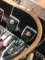
The issue was solved by moving the transistor onto the output transistor ... also there are controlled MCU fans at (start) 40 degrees Celsius so that the amplifier can not heat up in high demands keeping the bias 100ma per output transistor approximately constant.this is not a Wolverine problem, this is a passively cooled class AB relative to heatsink size problem?
The dimensions of my heatsink 28 X 16.5 X 5 cm
Last edited:
- Home
- Amplifiers
- Solid State
- DIY Class A/B Amp The "Wolverine" build thread