It’s a Cobra-S2 SMPS 🙂Can I ask which Micro Audio Cobra smps you are using. I can really benefit from your wiring schema as I have a modded S1. Good luck with the noise.
Are you not building EF3-3 ? There are no holes that need to be drilled for EF3-3 Drivers. Q104 is free air, and Q103 is remote mounted, which is what I think you were referring to, in your original post. I think Daniel thought you were building EF3-4. Just search ribbon cable on Amazon, you will find more then what you need there.Right. But that would require drilling a new hole. That skill is above my pay grade.

This is what I have used in the past - 3-pin Dupont connector/cable, Order the length you need (or longer) and cut to length, tin/solder bare wires to board and 3-pin female connector slides on to the TO-126 and TO-225 transistor legs.I'm looking for a grey ribbon cable to use to connect Q103 to the EF3-3 board. I'd appreciate a recommendation.
Thanks
Make sure you know which way you soldered the wire in - i.e. red wire is left leg, if transistor is facing you, or such.
Dupont cable
Hi Guys,
I'm probably over thinking this but I would like clarification on the note in the BOM for Q105 and Q106. Does the note mean the Toshiba Bipolar transistor doesn't like to see more than 70 V rails and the Onsemi can be used with an amplifier that has at least 65 V rails? If that's the case, then a Wolverine with nominal 71 V rails could use either of these devices (due to voltage losses in the circuit). Am I thinking about this correctly?
Thanks,
John
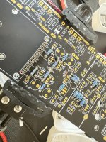
Got some more work done on the boards this weekend. Nearly finished the speaker protection boards from Felix and started placing a few components on the output stage… 🙂 Need to get moving on the enclosure soon, before I run out of work… 🙂
Attachments

If you look at the circuit diagram you will see that Q105 and Q106 are connected between the positive and negative rails. That is V+ plus |V-| in the worst case could appear across either collector-emitter junction. That is 140 volts for a 70 volt power supply. Toshiba will likely fail and it could be in a way that may take the drivers and outputs too.
Thank you Johno. I'm looking at the schematic for the EF3-X board. I do see Q105 and Q106 connected across the +/- power rails. The range across the rails is 49-71 Volts, and the upper end of the range tracks with what you saying about those devices potentially seeing 140 Volts, but won't each device see just half of that voltage? The example schematic shows +/- 64 Volt rails. It also shows Q105/106 as KSC3503/KSA1381. I am not sure what "Chq" next to them means. When I saw those devices listed as for >+/-65V it confused me.
I am trying to understand what I'm building. I'm reading Bob Cordell's book. Obviously I'm not an engineer, and a lot of what I read doesn't make complete sense to me. At the end of the day I'm just an implementor. I'm highly dependent on the Build Manual and the BOM.
I really do appreciate folks like you having the patience and willingness to answer questions.
John
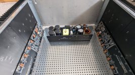
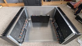
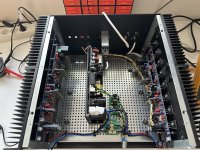
Hi, I read the conversation between Stuart and Ponti17 here. I am getting on nicely with my EF3-4 boards and thinking ahead to the wiring layout. I will be using a Cobra-S2, and would welcome advice on how best to orientate the SMPS? My pics show 2 possible layouts, then Ponti!7 has a very different idea with the longitudinal orientation (but with one side necessarily unshielded) - pic also copied here. Is there a best or worst place to put the Cobra? Advice from the experienced here very welcome!1. Watch Daniel's wiring video.
2. You don't have the safety ground from your input module connected to the chassis. It should be right near the input module.
3. Turn the ground lift around and connect the safety ground terminal to the same point on your chassis from above.
4. Run your output wires on the other side of your board, not next to the sensitive negative feedback path.
Regarding wiring, the document sent out with the GB says the RCA inputs should be as close as possible and be electrically and mechanically bonded. But on the Modushop rear panel they are very far apart, meaning each is temptingly close to the corresponding IPS input. But from what I have read this would increase the loop area, but if I run the input signal wires together to reduce loop area one is going to be really short and the other will travel right around the chassis. Is this OK? Is the T Ground just an option (if found necessary) or strongly advised from the outset?
One final small point: why do R133, R112 and R113 have an asterisk next to them on the board? I am worrried I am missing something.
Sorry to pile all these questions in together
Jonathan
Attachments
Johno is correct. Output rail can swing between almost V+ and almost V-. Collectors are fixed to rail. It's a triple emitter follower! Base of Q105 has 3 x Vbe distance to output rail, emitter only 2 x.Thank you Johno. I'm looking at the schematic for the EF3-X board. I do see Q105 and Q106 connected across the +/- power rails. The range across the rails is 49-71 Volts, and the upper end of the range tracks with what you saying about those devices potentially seeing 140 Volts, but won't each device see just half of that voltage? The example schematic shows +/- 64 Volt rails. It also shows Q105/106 as KSC3503/KSA1381. I am not sure what "Chq" next to them means. When I saw those devices listed as for >+/-65V it confused me.
I am trying to understand what I'm building. I'm reading Bob Cordell's book. Obviously I'm not an engineer, and a lot of what I read doesn't make complete sense to me. At the end of the day I'm just an implementor. I'm highly dependent on the Build Manual and the BOM.
I really do appreciate folks like you having the patience and willingness to answer questions.
John
Hello
I have made a new revision of the Speakerprotect board. First Revision published here https://www.diyaudio.com/community/...he-wolverine-build-thread.385920/post-7375013
This useful addition to the Wolverine Amp can protect connected speakers and the amp itself from destruction. This includes short circuit, overcurrent and overheating but also DC protection. On bad condition it disconnects speakers within milliseconds.
It also provides power on delay and immediate switches speakers off to prevent audible plops/noise while on/off.
The actual revision 1.0 has some useful enhancements and additions. It can now easy be used by either SMPS or linear PSU setups. Onboard four LEDs or single error LED display selectable by jumper, even remote bicolor LED can be used to show state.

Full documentation is available here: https://github.com/felix1024/SpeakerProtect
One board per amp channel is required.
PCBs and preprogrammed processors are available on request, just PM me.
-Felix
I have made a new revision of the Speakerprotect board. First Revision published here https://www.diyaudio.com/community/...he-wolverine-build-thread.385920/post-7375013
This useful addition to the Wolverine Amp can protect connected speakers and the amp itself from destruction. This includes short circuit, overcurrent and overheating but also DC protection. On bad condition it disconnects speakers within milliseconds.
It also provides power on delay and immediate switches speakers off to prevent audible plops/noise while on/off.
The actual revision 1.0 has some useful enhancements and additions. It can now easy be used by either SMPS or linear PSU setups. Onboard four LEDs or single error LED display selectable by jumper, even remote bicolor LED can be used to show state.
Full documentation is available here: https://github.com/felix1024/SpeakerProtect
One board per amp channel is required.
PCBs and preprogrammed processors are available on request, just PM me.
-Felix
Yes, but where is the problem? Recommended here OnSemi and Toshiba have sufficiently high Vce to handle PS of +/-71V. Yes, Toshiba's TTA/TTC have lower Vce than OnSemi KSA/KSC but still Toshibas have Vce = 160V so should handle 140V or so without problems. Am I right?Johno is correct. Output rail can swing between almost V+ and almost V-. Collectors are fixed to rail. It's a triple emitter follower! Base of Q105 has 3 x Vbe distance to output rail, emitter only 2 x.
I have no idea regarding the whereabouts of your problem. However the problem in message 4389 is clear, the poster assuming a Vce slightly over the singe rail voltage would be sufficient. So I explain to those involved or interested why this is not the case. If such an assumption is not corrected, there is a risk that others will adopt the idea. This is best avoided.
This is what I was looking for. I got the message loud and clear. I think the note in the BOMJohno is correct. Output rail can swing between almost V+ and almost V-. Collectors are fixed to rail. It's a triple emitter follower! Base of Q105 has 3 x Vbe distance to output rail, emitter only 2 x.
could be made clearer for non-engineers.
Many thanks,
John
ใช่แล้วทำไมจะไม่ได้ล่ะ..
นี่คือแผนผัง BOM และ PCB และโค้ดสำหรับ Tiny:
ฉันมี PCB เหลืออยู่บ้าง และสามารถจัดหา ATMega Tiny 84 ที่ตั้งโปรแกรมไว้ได้ตามคำขอ (PCB + Tiny ราคาประมาณ 10 ยูโรต่อชุด + ค่าขนส่ง)
HelloYes, why not..
Here is schematic, BOM and PCB and code for Tiny:
I have some leftover PCBs and can provide programmed ATMega Tiny 84 on request. (PCB + Tiny around € 10 per set + shipping cost)
View attachment 1182717
I have seen your protection kit and am interested, but I still don't understand. Ask as follows.
-J7 How to connect over current
-J6 How to connect to power supply.
Respect
Please consult the actual documentation here https://github.com/felix1024/SpeakerProtect
the document "Speaker Protect Interface.pdf" shows the details.
J6 connects to the Wolverine SIP header.
J7 connects to a NC bimetal temperature switch which opens at the desired max temperature (preferably mounted to the heatsink)
 bimetal switch NC, opens i.e. @60°C
 Wolverine SIP connector
Speaker Protect circuit measures current over NPN and PNP emitter resistors.
the document "Speaker Protect Interface.pdf" shows the details.
J6 connects to the Wolverine SIP header.
J7 connects to a NC bimetal temperature switch which opens at the desired max temperature (preferably mounted to the heatsink)
bimetal switch NC, opens i.e. @60°C Wolverine SIP connectorSpeaker Protect circuit measures current over NPN and PNP emitter resistors.
Asterisk means resistor should be raised - have space underneath it, installed with a 2mm min gap from the board, improves coolong.Regarding wiring, the document sent out with the GB says the RCA inputs should be as close as possible and be electrically and mechanically bonded. But on the Modushop rear panel they are very far apart, meaning each is temptingly close to the corresponding IPS input. But from what I have read this would increase the loop area, but if I run the input signal wires together to reduce loop area one is going to be really short and the other will travel right around the chassis. Is this OK? Is the T Ground just an option (if found necessary) or strongly advised from the outset?
One final small point: why do R133, R112 and R113 have an asterisk next to them on the board? I am worrried I am missing something.
Search YouTube for Daniel’s wiring vid - Wolverine wiring
Hi @mainframe99Asterisk means resistor should be raised - have space underneath it, installed with a 2mm min gap from the board, improves coolong.
Search YouTube for Daniel’s wiring vid - Wolverine wiring
Thanks very much for your reply. I'd figured the asterisk was probably just because the R133, R112 and R113 were higher wattage resistors, and had soldered them with an appropriate gap under them. I have done this for all the resistors >1/4W. There are quite a number more than those 3 though, and they don't have an asterisk on the PCB and that's what confused me. Thought I may be missing something.
I have watched all Daniels videos multiple times, but there are still some conflicts I haven't resolved. Thanks anyway though.
If your IPS inputs are close to the RCAs (you say they are) and you keep the wires as short as possible you shouldn't have any hum or interference - that's how the majority of people wire their amps, including myself and the Wolverine is one of my quietest amps in the collection.
You can use shielded cabling, and put the RCAs close together on one side and do all that is mentioned as well, but it would be going above and beyond what is necessary to have a very quiet amplifier.
The amp is inherently quiet without going to this added work, assuming your input wiring is away from AC currents and properly short. But these items you mention in the build guide will result in a lower noise floor, or help resolve any hum in your system if it occurs.
- Home
- Amplifiers
- Solid State
- DIY Class A/B Amp The "Wolverine" build thread