You can use these replacement transistors without problems but for Q1-2 these are not the best choice. I have some spare bc559 from Jaycar in Perth and I can post these to you in an envelope as a letter. If it's OK for you send me a message with your address.Hey guys,
I needed some help with the build I’m almost done it.
Where must these go I’m very confused. I got the entire component kit.
The build guide says,
Q1&2 - bc559 , (is BC-327 alternative)
Q3,4,12,14 - bc549 (available)(is bc-337 alternative )
Q5&6 - KSA992 (available)
Please refer to the image below (components for pair of boards)
cheers,
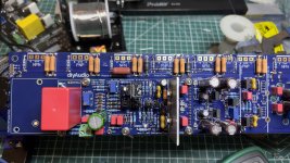
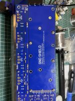
I have successfully started my testing on the Wolverine , the board turned on perfectly 4 lights on the IPS turned on the series lamp did not glow at all. No shorts . I measured voltage across TP107 & TP108 it reads 0mV not sure why cause all the other test point readings are perfect. I also tried adjusting the 500R trimpot (R109) but no hope and no change. Let me know what to look for @stuartmp @fireanimal

New update!!
Got few 0.5A fuses today I used 0.75A initially, now the -V rails fuse blew imminently the +V rail fuse remains intact. Not sure what to look for at this point. Please guide. I have attached detailed images of the board below
Got few 0.5A fuses today I used 0.75A initially, now the -V rails fuse blew imminently the +V rail fuse remains intact. Not sure what to look for at this point. Please guide. I have attached detailed images of the board below
Attachments
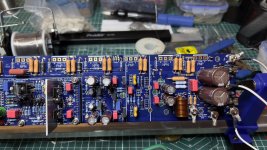
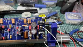
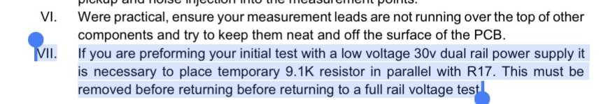
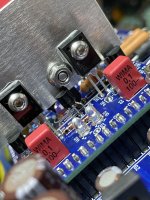
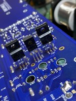
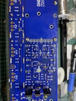
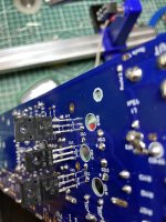
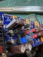
i cant tell 100% for sure, but it looks like the predrivers are installed backwards, and why cant I see the drivers through the OPS holes ? Bottom pics would be helpful
Have a look at these images I haven’t bent them yet as I haven’t ordered the heatsinks for them.
Attachments
-
 IMG_2006.jpeg545.1 KB · Views: 96
 -
 IMG_2007.jpeg431.8 KB · Views: 104
 -
 IMG_2008.jpeg589.9 KB · Views: 89
 -
 IMG_2009.jpeg575.4 KB · Views: 93
 -
 IMG_2010.jpeg508.6 KB · Views: 93
 -
 IMG_2012.jpeg391 KB · Views: 104
 -
 IMG_2013.jpeg427.7 KB · Views: 91
 -
 IMG_2014.jpeg386.2 KB · Views: 93
 -
 IMG_2015.jpeg418.9 KB · Views: 98
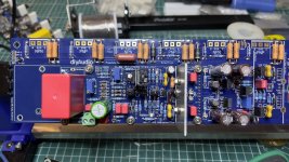
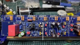
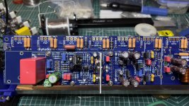
You better verify all transistors I am seeing more installed wrong. Verify all pinouts with the datasheets, those transistors will also need to be tested

I had installed Q106 wrong it has been corrected , I have checked all transistor, diodes and caps it’s perfect.
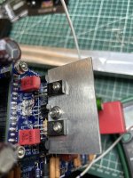
Sorry it was the picture that was throwing off my orientation of the drivers. So now do you have bias ?
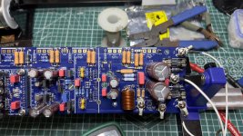
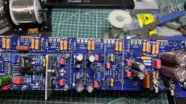
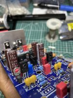
more pics of corrected transistors? I'm seeing around the wrong way also.
In this picture, both Q105 and Q106 are around the wrong way, you mentioned you only corrected Q106

In this picture, both Q105 and Q106 are around the wrong way, you mentioned you only corrected Q106
yeah more then just Q106 from what I can tell. A close up please of all transistors would be great, front and back
- Home
- Amplifiers
- Solid State
- DIY Class A/B Amp The "Wolverine" build thread