^ What's confusing you? I literally just demonstrated that it can be done... the fact that there is not a button seems to be your point. That does not in any way prevent someone from quoting a previous post. Once again, I will demonstrate.

Seriously, guys, this is really funny. I wasn't highlighting a design flaw and trying to send this excellent build guide off-topic. I was on my phone and thought I would say, "I can't quote you", but thank you for responding.
The UX of the quote feature makes sense. I haven't encountered forum functionality like that before, but now I know, so lesson learned, intermission over, back to build guide.
The UX of the quote feature makes sense. I haven't encountered forum functionality like that before, but now I know, so lesson learned, intermission over, back to build guide.
😉The UX of the quote feature makes sense. I haven't encountered forum functionality like that before, but now I know, so lesson learned, intermission over, back to build guide.
Look at MicroAudio, as well. They likely have an option for monoblock Wolverines. Their products are well regarded and they will work with you to get what you need. You’ll likely have to contact them via the site to request a specific output voltage.wolverine using SMPSs
The practice of not quoting the last post of a thread goes back to the early days of online forums. Access was usually over metered telephone lines (pay per minute or pay per kilobyte). With the increasing popularity of the net, came the arrival of a certain type of user, often referred to as AOL. Who had the annoying habit of quoting a lengthy previous post in its entirety and then writing something like 'me 2' underneath it.Seriously, guys, this is really funny. I wasn't highlighting a design flaw and trying to send this excellent build guide off-topic. I was on my phone and thought I would say, "I can't quote you", but thank you for responding.
Well done finding the problem David, I am happy for you, it can be really frustrating to find something like this sometimes.Today I had some time and checked the board. Solved the problem. I used bc559 instead of 549 for q12 and q14.
After change everything worked properly
Hope you enjoy the rest of the build and get a listen soon.
-Dan
Dan yes, it is frustrating. You check every part with multimeter before instal on the board, than you check it again. And at the end you made such stupid mistake.... and you can't see the part number, because is facing the heasink.
But at the end everything is ok. The main problem is time, I don't have all the time I would like to have to continue the work, to finish the build.
But at the end everything is ok. The main problem is time, I don't have all the time I would like to have to continue the work, to finish the build.
I'm doing chapter 17 of the build guide for my EF3-3. My minimun bias setting measured across R111A and R111B is 1180mV , the guide say it should be 750-800mV. R109 is 500R and I'm using BD139 for Q103 and Q104, R105 2K, R106 1,6K, R107 1.4K, R108 560r, RCC 56r. The video guide say the result can vary. Is mine a too big variation?
Do you have this values on both chanels / boards?
I had 550mV on mine.
I think that if you can go to 1,4V with trimmer (the end setting for operation), and bias is changing if you heat the transistor on wires by touching it it should be ok. But I'm not one of wolverine team, so somebody else should answer this.
I had 550mV on mine.
I think that if you can go to 1,4V with trimmer (the end setting for operation), and bias is changing if you heat the transistor on wires by touching it it should be ok. But I'm not one of wolverine team, so somebody else should answer this.
my bad actually I checked the resistor and R105 was wrong was 3.3K instead of 2K but now the bias is 400mV
Nice work Patriz, good to catch this before installing the outputsmy bad actually I checked the resistor and R105 was wrong was 3.3K instead of 2K but now the bias is 400mV
Hey guys,
I needed some help with the build I’m almost done it.
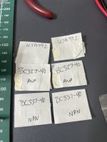
Where must these go I’m very confused. I got the entire component kit.
The build guide says,
Q1&2 - bc559 , (is BC-327 alternative)
Q3,4,12,14 - bc549 (available)(is bc-337 alternative )
Q5&6 - KSA992 (available)
Please refer to the image below (components for pair of boards)
I needed some help with the build I’m almost done it.
Where must these go I’m very confused. I got the entire component kit.
The build guide says,
Q1&2 - bc559 , (is BC-327 alternative)
Q3,4,12,14 - bc549 (available)(is bc-337 alternative )
Q5&6 - KSA992 (available)
Please refer to the image below (components for pair of boards)
Attachments
^ A bit more context please. Where you got those from and what transistors are still missing on your boards.
Got them from @fireanimal. They are replacements for bc549 &559. Got it cleared thanks
I ran into another issue now
To do the initial testing with power we require a 9.1K resistor which isn’t available here is there any other alternative to this.
I have a dual 30,35 &55v PS in hand
I ran into another issue now
To do the initial testing with power we require a 9.1K resistor which isn’t available here is there any other alternative to this.
I have a dual 30,35 &55v PS in hand
You might get away with a 10k resistor. However I can't offer hands on experience as I did not follow this procedure.
- Home
- Amplifiers
- Solid State
- DIY Class A/B Amp The "Wolverine" build thread