
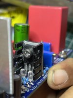
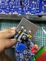
Just to clarify your asking about EF3-4 mounted Perpendicular to the heatsink is that right? When setting the new bias resistor values, I only tested and verified the EF3-3 and EF3-4 mounted directly on the heatsinks.
Sorry I have been very busy and didnt have much time on the forum.
Sorry I have been very busy and didnt have much time on the forum.

still no go or all g now?
(just remember Q103 will need to go back to other side of PCB for correct coupling with heatsink, I overheated some outputs by not thermally coupling Q103 correctly last year due. Obv you'll figure this out because you'll need to remove drivers and Q103 to get correct heights for heatsink mounting anyway)

(just remember Q103 will need to go back to other side of PCB for correct coupling with heatsink, I overheated some outputs by not thermally coupling Q103 correctly last year due. Obv you'll figure this out because you'll need to remove drivers and Q103 to get correct heights for heatsink mounting anyway)
Last edited:
thanks for your reply @mainframe99 , I have temporarily mounted Q103 just to get the board running. But no hope i tried and checked all possible components and it seems to be right as far as i see.
As you’ve sent me transistors for a pair of boards , I swapped all of them out and currently the new set is installed
If fuses are blowing, it is likely due to installing some transistors around the wrong way which has likely sent current flowing down paths it shouldn't have, and now there are shorts to ground through blown components. As to the extent of this, I cannot say, but transistors will need to be removed and tested, followed by diodes, near the areas of fault (in this case, maybe start at drivers? - you haven't got output transistors installed yet, correct?)
Remove the boards from power and go back to step 16.3 of build guide. (r41) report back results.
Remove the boards from power and go back to step 16.3 of build guide. (r41) report back results.
I haven’t installed the outputs yet I’ll just perform what you’ve suggested and get back. Hope to see some progress
And after the fuses blew I have swapped every transistor with new ones. I don’t think it’s the transistors fault anymore it’s probably other damaged components
you may need to start a line with one of the build team, if they dont reach out, as its getting beyond my ability, but I would start looking at diodes, if you are certain your transistors are 100% good. As you said earlier, you only corrected 1 transistor when 2 people pointed out that you had 2 obviously inserted wrong, so you need to be certain you are getting you components installed the right way around and they are functioning. Do you have a component tester (sorry if you mentioned earlier that you do)
Nope I do not have a component tester I use my LCR for testing is that fine ?
And yes Andy and Stuart have been helping me and Andy is busy I’m just being patient. I’ll check the diodes Is there any particular method with a LCR?
Thank for your time and patience. I’m honestly an amateur this is my first project.
And yes Andy and Stuart have been helping me and Andy is busy I’m just being patient. I’ll check the diodes Is there any particular method with a LCR?
Thank for your time and patience. I’m honestly an amateur this is my first project.
Ok good, Diodes just check with a multimeter, in diode mode, OL one way and around 0.5-0.7 the other way
- Home
- Amplifiers
- Solid State
- DIY Class A/B Amp The "Wolverine" build thread