Also I just noticed, you need to remove those nuts holding the IPS on, there is not enough clearance there.
I’m finally seeing bias of 710 mV. Now the question is was it the fuses or have I done something wrong
I would swap the red ones back in, there are just not for indication. When you install the red ones then verify that the ones on the output are installed correctly
You need female standoffs and screws
You need female standoffs and screws
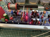
Huge update ,
Bais is stable at 1.4V
DCO- 0mV
CCS2- 610mV
The drivers have no heatsink on them yet and they are getting hot is it normal ?
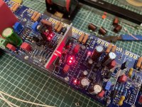
Bais is stable at 1.4V
DCO- 0mV
CCS2- 610mV
The drivers have no heatsink on them yet and they are getting hot is it normal ?
Those LED's are not just for fun, they are used as voltage reverence. And blue LED's have an other voltage over them as red ones.Yes I have swapped the LED's to blue to match the board

Does this have to be exact
"Voltage between TP-105 (DMM -) and the positive power rail connection should read about 1.7 V if you are using the TTC004B transistor for Q101"
I'm getting 1.3V
"Voltage between TP-105 (DMM -) and the positive power rail connection should read about 1.7 V if you are using the TTC004B transistor for Q101"
I'm getting 1.3V
You need to slow down, more attention to detail. It's exciting getting close to the finish, but also where most mistakes are made. You are making good progress, and your solder work looks good.
Reread this excerpt from the build guide - slowly:
"It should read about 1.5 V if you are using the TTC004B transistor for Q101"
(..... 1.7V is for a cap multiplier using the 3503 transistor.)
Anyway, 1.3V could be okay, if you are using test rail voltages that are lower than your final rail voltages. I have had 1.4V in this case before with no problems. Could even be multimeter accuracy.
What are your testing voltages?
What are your target final rail voltages?
Did you select all the correct parts for these rail voltages? R6, R15, R17, R23, R24. Rled1 and Rled2. (I understand this is Andys kit, so I know he gave you the correct parts, but as we now know, you've been changing them on a whim)
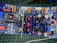
Looks like you are sorted now though. Don't test those drivers for long without a heatsink.
And yup, the blue LEDs certainly sent everyone on a goose chase. If a build guide has an LED color, it's for a reason see:

Blue is WAY off.
Yes, I know it is nice to choose your favorite colors. But silicon doesn't give a damn about your favorite colors 😀
Reread this excerpt from the build guide - slowly:
"It should read about 1.5 V if you are using the TTC004B transistor for Q101"
(..... 1.7V is for a cap multiplier using the 3503 transistor.)
Anyway, 1.3V could be okay, if you are using test rail voltages that are lower than your final rail voltages. I have had 1.4V in this case before with no problems. Could even be multimeter accuracy.
What are your testing voltages?
What are your target final rail voltages?
Did you select all the correct parts for these rail voltages? R6, R15, R17, R23, R24. Rled1 and Rled2. (I understand this is Andys kit, so I know he gave you the correct parts, but as we now know, you've been changing them on a whim)
Looks like you are sorted now though. Don't test those drivers for long without a heatsink.
And yup, the blue LEDs certainly sent everyone on a goose chase. If a build guide has an LED color, it's for a reason see:
Blue is WAY off.
Yes, I know it is nice to choose your favorite colors. But silicon doesn't give a damn about your favorite colors 😀
Last edited:
- Home
- Amplifiers
- Solid State
- DIY Class A/B Amp The "Wolverine" build thread