Stuart how are you matching those higher power transistors?I bought 100 bc559cta, 100 bc549cta and 100 ksa992fta and matched them by a DCA75. I chose the best couples and Stuart kindly matched for me two couples for Q105/Q106. No more. That amp is simply stunning.
Gaetano.
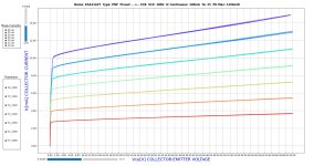
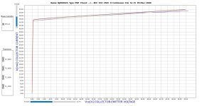
@fireanimal @danieljw and I have designed a built our own fully programable dynamic current tracer. It can curve trace small signal and output transistors.Stuart how are you matching those higher power transistors?
Attachments

Please give this to us 😉@fireanimal @danieljw and I have designed a built our own fully programable dynamic current tracer. It can curve trace small signal and output transistors.
I'm afraid it's a device you connect to an oscilloscope or computer having compatible oscilloscope application installed. I bought a tracer device long time ago to match mosfets. I should still have it somewhere but have only a vague memory how to use it.
Of course one can build such a device having it's circuit diagram.
Of course one can build such a device having it's circuit diagram.
I am of course biased, but I can say that it works very well. It's in the public domain, so anyone can use it. More here:What do you think of PyPsuCurvetrace, the Python script developed by @mbrennwa for transistor curve tracing using two programmable PSU?
https://pypsucurvetrace.readthedocs.io/en/latest
Accuracy is determined by the accuracy of the meters in the PSUs. If that's not enough, you can specify your own calibration to pypsucurvetrace.
One cool aspect is that pypsucurvetrace allows controlling the temperature of the DUT, which is crucial for testing of power transistors.
Last edited:
What are the operating points of the following devices?
1) Q1 and Q2
2) Q3 and Q4
3) Q5 and Q6
4) Q105 and Q106
5) Q107 and Q108
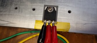
My idea for matching the transistors is to use two power supplies, a couple of resistors and a meter to measure Vbe and beta at the operating point.
1) Q1 and Q2
2) Q3 and Q4
3) Q5 and Q6
4) Q105 and Q106
5) Q107 and Q108
My idea for matching the transistors is to use two power supplies, a couple of resistors and a meter to measure Vbe and beta at the operating point.
Last edited:
before I start buying parts in earnest I thought id see if anyone has any spare matched resistors they would like to part with? I'm looking for CMF55 matched resistors for R3/4 100r will need 2 pairs for these and R7/8 220r again would need 2 pairs. Does anyone have them?
Funny.... I tend to find best suited Dale RN60 pairs when building stuff...
But honestly, it's probably not needed with 1% or better 🙂
But honestly, it's probably not needed with 1% or better 🙂
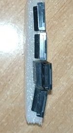
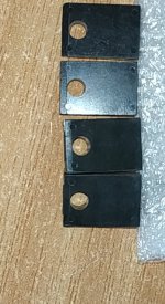
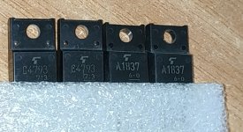
Μy new drivers have arrived
We'll see if we hear anything different about them
to Mje15034_35.
We'll see if we hear anything different about them
to Mje15034_35.
Attachments
Last edited:
I went the other way (from 2SC/2SA to MJE32/33) interested what your listening impressions are.
Voltage rails?
Voltage rails?
Voltage rails 57V.
My output transistor are Toshiba 2sc5359 2sa1987.
and in accordance with the instructions SOA the volts for these transistors according to instructions from member Harry3 (Γεια σου φιλε μου ) must be about 40-42VAC.
I have two toroidal 2X42V /230Vac 400VA and with the sag gives me about 57Vdc.
I hope to hear something better than the best.
Last edited:
Hi guys, I need some help with the psu design for a two channels wolverine. Is it correct to say that I have the following options?
1) Single transformer with dual secondaries PSU, with one DC+ and one DC- outputs: in this case I connect the two V+ rails of the two channels to the DC+ output of the psu, and the two V- rails of the two channels to the DC- output of the psu.
2) Two transformers with dual secondaries PSU: in this case each transformer has a DC+ and a DC- output. So, the rails V+, V- of each channel are connected to the DC+,DC- outputs of each transformer, respectively. Basically, each transformer separately serves each channel.
Then I have the following further distinction: in both case 1) and case 2) if the two secondaries are center tapped I use a single bridge rectifier, whereas if I have two "separate" secondaries I need a bridge rectifier for each secondary. It follows that I have the following choices:
single transformer + center tapped dual secondaries -> single bridge rectifier;
single transformer + separate dual secondaries -> two bridge rectifiers;
two transformers + center tapped dual secondaries -> one bridge rectifier for each transformer (total of two bridge rectifiers);
two transformers + separate dual secondaries -> two bridge rectifiers for each transformer (total of four bridge rectifiers);
Is it correct? Which of these solution is preferred?
Last edited:
Ok so single transformer is nice in that it is a simple clean layout and you could maybe have one much larger transformer for similar cost...
Dual transformer allows "dual mono" layout but it does require 2 sets of 2 bridge rectifiers, capacitors banks and some more mounting hardware etc. etc.
I have had good results with either layout.
But I chose dual mono for my Wolverine build.
Something to consider is a switchedmode power supply also.
- Dan
- Home
- Amplifiers
- Solid State
- DIY Class A/B Amp The "Wolverine" build thread